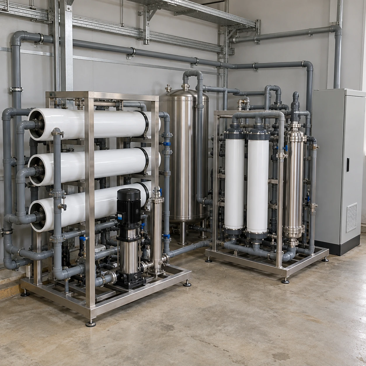
Ultrapure Water Systems
ultrapure water systems for semiconductor plants
| Plant arrangement | Modular make-up, polishing, storage and return-loop equipment |
|---|---|
| EDI skid envelope, L × W × H | Approx. 1905 × 1016 × 2032 mm |
| Expanded EDI skid envelope, L × W × H | Approx. 3200 × 1219 × 1803 mm |
| Capacity definition | Net accepted make-up and circulation duty stated separately |
| Continuity options | Parallel or standby equipment with defined isolation boundaries |
| Controls | Quality, flow, pressure and tank-level monitoring with agreed alarm response |
The dimensions apply to EDI subassemblies, not a complete semiconductor water plant. Tanks, RO equipment, final polishing and service aisles add to the installation footprint.
Equipment grouping, loop interfaces and expansion provisions can be customized to the semiconductor plant's approved operating requirements.
Semiconductor plant water equipment must work across changing tool demand and maintenance states. Define make-up, polishing and distribution duties separately, then coordinate their interfaces and expansion provisions.
Design around the plant's operating states
Ultrapure water systems for semiconductor plants must connect water treatment to a changing production load. Normal circulation, tool startup, maintenance and future expansion place different demands on the same equipment. The task is to deliver accepted water consistently while keeping the installation serviceable. A collection of individually adequate skids can still fail to meet that objective when their interfaces are poorly matched.
Describe the plant as a set of water users with defined delivery requirements. Include the existing process tools, planned additions and any uses that can be served by a different grade. Avoid treating all utilities as one ultrapure demand; it can add unnecessary load and obscure which connections are truly critical.
Give make-up, polishing and distribution separate duties
- Make-up treatment: remove the incoming contaminant load and replenish the water consumed or rejected. Its design depends on source-water quality and operating conditions.
- Storage and polishing: buffer appropriate short-term demand and maintain the selected quality through the defined treatment path. Storage volume must be considered with turnover and available maintenance arrangements.
- Distribution and return: deliver water at the required tool connections and maintain the intended loop operation when draw changes. Pressure losses, branch conditions and return monitoring belong to this duty.
The public description of Veolia's semiconductor UPW systems identifies RO, EDI and polishing as elements of this field. A project's final sequence and acceptance limits must be established from its own design basis; another supplier's published performance is not a guarantee for the equipment selected here.
Calculate the load that each part actually sees
Net make-up demand includes water consumed by tools and losses associated with the selected operation. Loop circulation can be much greater than the volume consumed. Size each duty explicitly so that a large circulation-pump rating is not mistaken for fresh production capacity.
Evaluate the busiest relevant period alongside normal demand. A buffer can carry a brief peak, but it cannot indefinitely replace insufficient treatment capacity. Likewise, a system selected only for the ultimate expansion may spend its early life at a low load that needs a deliberate operating strategy.
Check continuity beyond the spare pump
Redundancy should be judged by what remains available while a component is isolated. Shared tanks, valves, power and controls can limit the usefulness of parallel treatment trains. Define the acceptable operating state during maintenance before choosing how much duplicate equipment to buy.
Leave expansion interfaces that can be used
An expansion allowance needs more than an empty patch of floor. Reserve access for membrane withdrawal, cartridge replacement, electrical panels and lifting routes. Identify where new treatment capacity and new user branches can connect, how those sections will be isolated and how the altered wetted path will be brought into service.
Use the current layout to decide where instruments and sample points can distinguish a treatment deviation from a distribution problem. The loop return, the treatment outlet and selected user connections provide different information. A single central sensor cannot explain every local event.
Keep the water balance and drain scope visible
RO concentrate, flushing, maintenance discharges and rejected startup water have to reach appropriate receiving systems. State these flows separately from useful production. Proposed recovery or reuse should identify the stream, its variable composition and the treatment needed before its next use. Do not connect an uncertain return stream to the accepted-water supply merely to improve a headline recovery number.
A facility enquiry should combine the source analysis, water-user schedule, utility layout and intended expansion sequence. The provider comparison page helps divide package and site responsibilities, while wafer-processing selection addresses the quality endpoint. shengtongjh can use that defined scope to coordinate the equipment enquiry without implying responsibility for an unagreed complete fab project.
Equipment grouping, loop interfaces and expansion provisions can be customized to the semiconductor plant's approved operating requirements.