Ultrapure Water Systems
best ultrapure water systems for semiconductor wafer processing
| Selection basis | Tool water specification and agreed analytical methods |
|---|---|
| Treatment formats | Central make-up and polishing; application-matched point-of-use treatment |
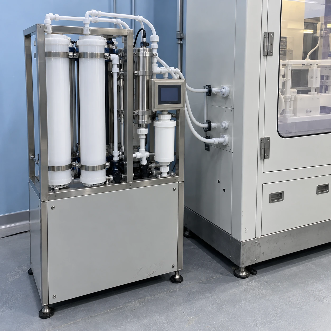
| EDI stage envelope, L × W × H | Approx. 991 × 1041 × 2032 mm or 1905 × 1016 × 2032 mm |
| Quality parameters | Resistivity, TOC, particles and process-specific chemical limits |
| Wetted path | Materials and connections selected for purity, cleaning and temperature |
| Acceptance location | Defined system outlet and relevant process-tool connections |
The dimensions describe EDI-stage equipment only. Local polishing assemblies and the complete installed system are sized to the approved process duty.
The treatment and monitoring configuration can be customized to the wafer process, upstream water and required tool interfaces.
Select wafer-process water equipment by the quality required at the tool, the incoming water and the operating duty. A useful comparison covers the full contaminant profile and the delivery conditions.
“Best” starts with the wafer process
The best ultrapure water systems for semiconductor wafer processing are those matched to the actual process specification and able to maintain it at the tool connection. There is no universal winner based on resistivity, membrane count or cabinet size. A pilot wet bench, a production rinse and a process-development laboratory can place very different demands on water quality, peak delivery and continuity.
Compare the contaminants that can reach the wafer
| Concern | Selection question | Evidence to compare |
|---|---|---|
| Ionic contamination | Does the selected train address the relevant dissolved species? | Resistivity trends plus application-specific chemical measurements, with temperature conditions stated |
| Particles and colloids | What must be removed before water reaches the process? | Particle size thresholds, counting method, sampling arrangement and filter retention information |
| Organic contamination | Are background carbon and particular compounds important to the recipe? | TOC monitoring and any specific analysis required by the process owner |
| Trace metals, silica or boron | Which individual species have process limits? | Relevant detection limits and measured results at the agreed location |
| Delivered condition | Does the tool require controlled temperature, dissolved gases or pressure? | Conditions measured during the intended tool operating states |
The contaminant categories above are consistent with the treatment challenges described by DuPont's microelectronics water guidance. They are not a universal limit table: the process owner must define the applicable values and methods.
Choose a treatment path that fits the gap
Where incoming water still carries a substantial dissolved load, bulk treatment must do its work before a final polisher. Adding a small point-of-use cartridge to an unsuitable supply can consume media quickly while leaving other contaminants uncontrolled. Where the central supply already meets most requirements, local polishing may instead address the last part of the path to a sensitive tool. Those are different purchasing problems.
Central polishing
A central system can serve several tools and concentrate maintenance in one utility area. Its distribution loop becomes part of the quality boundary. Pipe materials, connection work and changes to the loop must therefore be included in the commissioning and operating plan.
Point-of-use treatment
A local assembly can place a selected treatment barrier close to the process. It adds its own pressure loss, service requirement and replacement schedule. Specify the upstream water it can accept and the outlet condition it must achieve; proximity to the wafer does not by itself establish purity.
Ask for performance under changing demand
Water accepted during steady circulation may behave differently when several tools call for water together or after a maintenance intervention. A meaningful comparison includes the operating states that matter to the line. Identify the maximum simultaneous draw, the minimum routine load and the response to an out-of-limit condition. The agreed controls should prevent off-specification water from being treated as accepted production simply because a pump is running.
Sampling deserves the same care as treatment. A long sample tube, an unsuitable vessel or an unrepresentative sampling point can obscure the source of a deviation. Locate online instruments and sample points where they help distinguish central treatment, loop and local connection problems. Include instrument suitability and calibration in the acceptance plan.
Make the final comparison on usable production
Compare the cost of supplying water that the process can actually use, including rejected startup water, consumables, maintenance access and interruptions. A more elaborate train is justified only when its additional stages address an identified requirement. Equally, deleting a stage to reduce the purchase price is poor value if the resulting water cannot be accepted at the wafer tool.
For a quotation, pair the tool water specification with a demand schedule and the existing supply analysis. The fab procurement page explains how to turn those requirements into a defined equipment and acceptance scope.
The treatment and monitoring configuration can be customized to the wafer process, upstream water and required tool interfaces.