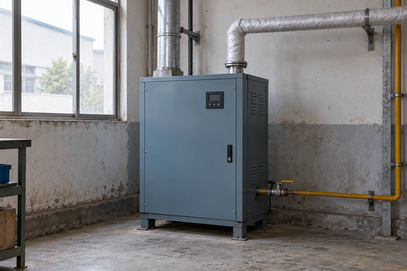
Steam Humidifiers
gas fired steam humidifiers
| Heating method | Gas burner and heat exchanger heating water in a separate steam tank |
|---|---|
| Compact gas-heated options | 23, 34 or 45 kg/h; overall 590 × 590 × 1085 mm (L × W × H) |
| Intermediate gas-heated option | 68 kg/h; overall 819 × 590 × 1085 mm (L × W × H) |
| Larger gas-heated options | 91, 113 or 136 kg/h; overall 1422 × 559 × 1194 mm (L × W × H) |
| Fuel selection | Natural gas or LP configuration matched to the approved burner and local supply |
| Steam distribution | Separate atmospheric steam outlet to duct dispersion or room distribution |
| Water and drainage | Compatible feed-water treatment, tank drainage and flue-condensate provision for condensing designs |
| Utilities and controls | Gas, combustion air, approved flue route, electrical controls and humidity interlocks |
L and W describe the unit's two horizontal footprint dimensions; H is its overall unit height. External connections, optional supports, flue routing and service access require additional space. Output and utility requirements are established in the selected equipment specification.
Gas-fired steam humidifier configurations can be matched to your moisture load, fuel supply and installation conditions.
Gas fired steam humidifiers use a burner and heat exchanger to boil water for humidification. They can be considered for substantial or sustained moisture demand where the gas supply and installation space are suitable. The choice involves the whole utility arrangement, including combustion air, exhaust venting, water and steam delivery.
Keep the combustion circuit and moisture circuit distinct
The burner supplies heat through a heat exchanger. The water in the humidifier tank becomes steam for the air system.
Combustion products leave through the appliance flue. Humidification steam leaves through its own outlet and distribution pipework. These serve different functions and require separate, correctly specified routes.
This distinction matters when the unit is placed near an air handler. The convenient point for a steam connection may not offer a suitable flue termination or combustion-air route. Establish both paths before committing to the equipment position.
Assess the installation through three interfaces
Fuel and burner
Match the gas type and available supply to the selected appliance. Other gas equipment operating at the same time can affect the site supply requirement. Burner suitability and commissioning belong to the approved configuration and qualified installer.
Combustion air and flue
Room-air and sealed-combustion arrangements have different installation implications. The flue material, routing and termination must follow the selected appliance requirements and local rules. A nearby wall opening alone does not establish a compliant route.
Water and steam
Choose water treatment for the tank and operating duty. Route the steam to a distribution assembly that suits the airflow, with a planned condensate path and access to the components that need regular attention.
Compare running cost on the same basis
A lower fuel tariff does not by itself establish a lower whole-system cost. Compare the expected annual moisture duty, time at part load, installation work, water use and maintenance. Include auxiliary electrical consumption and any treatment equipment in the comparison.
Published gas efficiencies can use different fuel-energy conventions. Higher-heating-value and lower-heating-value figures cannot be compared as though they were the same measurement. Use one consistent basis and the actual selected appliance data when evaluating alternatives.
Condensing equipment adds a drainage task
A condensing gas design recovers additional heat from its exhaust. The resulting flue condensate needs a drainage arrangement suitable for the appliance, its discharge properties and local requirements. This is a separate issue from the water removed during tank maintenance.
Keep the different drains identifiable and accessible. Appropriate materials, routing and any required neutralization should be resolved during installation design. Improvised connections can make a small service problem difficult to trace later.
Evaluate the minimum as well as the maximum load
A unit chosen for a large winter requirement may spend many hours at a much smaller demand. Check its modulation range and operating sequence against those hours. Where several generators are used, sequencing can share work and organize maintenance, but the remaining capacity must suit the process if a unit is stopped.
Allow access to both sides of the duty
Water-side scale management and combustion-side service are separate maintenance needs. The layout should allow each without obstructing the other. Keep removal space around covers and assemblies, and provide safe access to the isolation points and drain connections.
Specify a complete humidification package
For process applications, review the continuity requirements described under industrial steam humidifiers. If the project is still comparing heat sources, the broader steam humidifier selection explains the electric alternatives.
A quotation can be developed around the moisture load, fuel type, available services, proposed flue and steam routes, operating schedule and control interface. Appliance ratings and installation requirements are established for the selected configuration.
Gas-fired steam humidifier configurations can be matched to your moisture load, fuel supply and installation conditions.