Steam Humidifiers
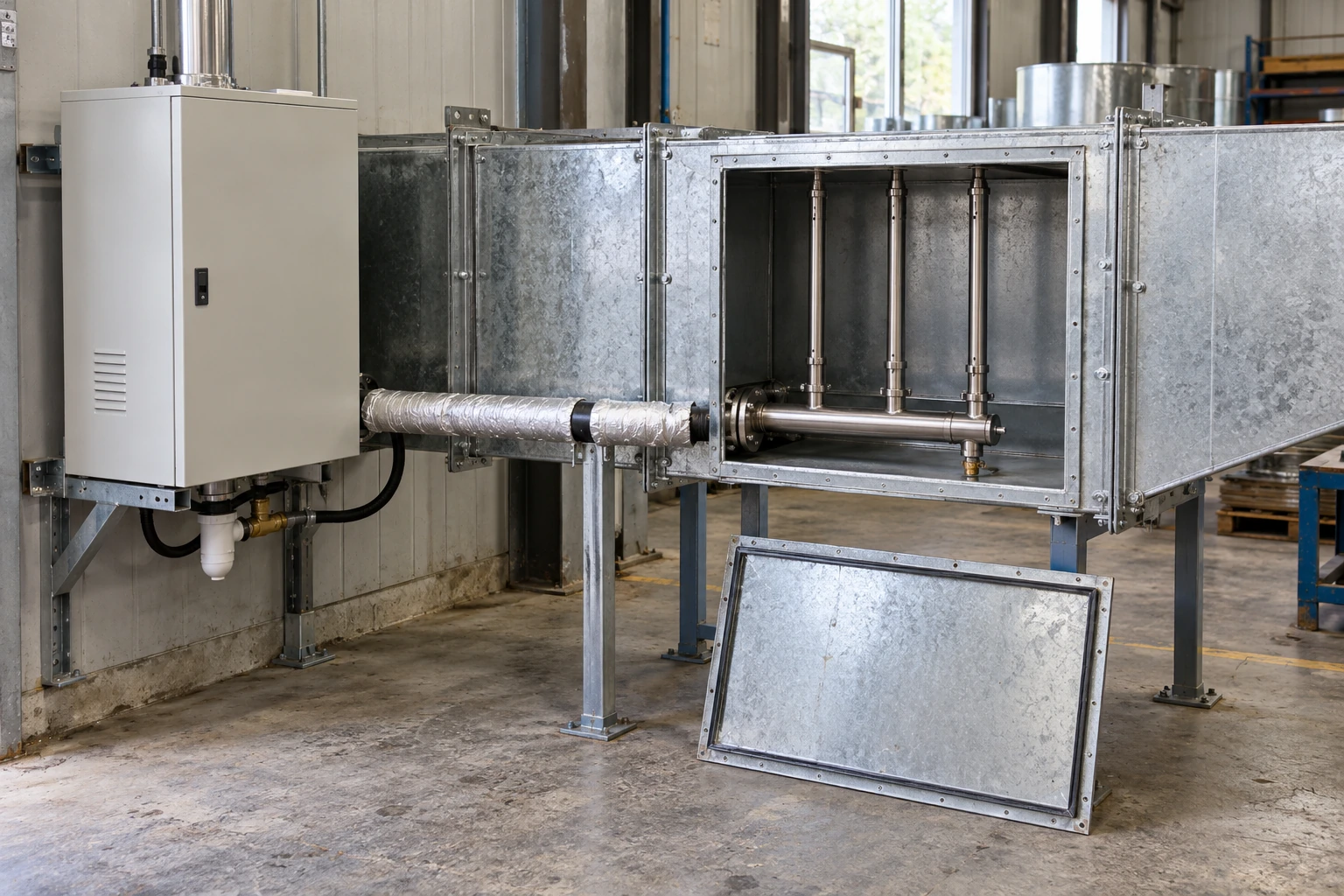
commercial duct mounted steam humidifiers
| System arrangement | Steam generator outside the airstream, connected to an in-duct dispersion assembly |
|---|---|
| Compact electrode options | 5 or 9 kg/h; cabinet 371 × 221 × 523 mm (W × D × H) |
| Medium electrode options | 14 or 22 kg/h; cabinet 452 × 302 × 612 mm (W × D × H) |
| Larger electrode options | 34 or 45 kg/h; cabinet 505 × 340 × 650 mm (W × D × H) |
| Dispersion format | Single lance or multiple tubes matched to duct cross-section and airflow direction |
| Condensate provision | Drainable steam route and distribution assembly; return or drain arrangement by generator compatibility |
| Control package | Humidity demand, proven airflow and duct high-limit protection |
| Installation access | Duct inspection opening, supported connections and generator service clearance |
Listed sizes are electrode generator cabinets, not duct openings. Dispersion width, tube length and absorption space are selected from the actual duct and operating air conditions. Output and utility requirements are established in the selected equipment specification.
The generator and duct-mounted distribution assembly can be configured to suit your ventilation system, moisture load and available installation space.
Commercial duct mounted steam humidifiers normally combine a steam source beside the ventilation system with a dispersion device installed in the duct. The cabinet produces steam; the lance or tube assembly introduces it into the airstream. Both parts must suit the airflow, moisture load and available mixing space.
Mount the right component in the duct
The dispersion assembly belongs in the airstream. The steam generator needs its own supported position with access to power, water, drainage and service components.
Keeping the generator close to the delivery point can simplify the steam route. Mounting it on an air handler or adjacent wall still requires the correct support and environmental protection. An indoor cabinet should not be exposed outdoors simply because the duct is outdoors.
The duct installation also needs access to the distributor and its connections. A permanently sealed section can make a minor drainage or maintenance problem difficult to investigate.
Absorption distance is a selection result
Steam introduced into cooler air can form a visible plume before it is fully absorbed. The available downstream space must allow that process to finish before the plume reaches a filter, elbow, damper, fan or other surface that can collect moisture.
The required distance changes with entering-air temperature, humidity, steam load and the dispersion arrangement. There is no single clearance that fits every commercial duct. Evaluate the limiting operating condition, including low airflow or cooler supply air, rather than relying only on the normal daytime condition.
Choose a dispersion arrangement for the available space
Single lance
A single tube can be practical for a modest load where the duct geometry and downstream distance permit adequate mixing. Its insertion length and outlet arrangement need to suit the cross-section, rather than merely fitting through the side wall.
A wide duct does not receive uniform moisture simply because a short tube enters it. Airflow distribution and the manufacturer's selection limits remain part of the choice.
Multiple tubes
Several tubes can distribute the steam over more of the air path and reduce the mixing distance needed for a particular duty. This is useful when the load or space restriction makes a single lance unsuitable.
The assembly also occupies duct space and needs a suitable header, support and drainage arrangement. Check the complete assembly and access requirements, not only the tube spacing.
Give condensed water a deliberate route
Some vapour condenses in the connecting steam line and in the distribution hardware, especially during warm-up. Pipe support, pitch and drain connections should follow the selected generator and distributor instructions. A sagging hose can collect water even if both ends are in the correct positions.
Do not assume all condensate should return to every generator. Some arrangements allow return to the tank; others require a separate drain. The correct route depends on generator compatibility, pressure conditions and the distribution design. Coordinate it before closing the duct or ceiling.
Coordinate three different control jobs
- Demand
- The room or system controller requests moisture to maintain the required condition. Its sensor location should represent the controlled area.
- Permission
- Airflow proving establishes that the ventilation system is moving air through the distribution section. Fan command alone may not prove that suitable airflow is present.
- Limitation
- A duct high-limit device restricts or stops steam before the local air becomes too humid. Its location must allow a representative reading after the relevant mixing distance, in accordance with the control design.
These functions become especially important when a variable-volume system reduces airflow. A continuing room demand does not override the duct's reduced ability to accept moisture.
Make the installation review specific
Record duct width and height, airflow direction and range, entering-air temperature and humidity, the proposed moisture addition and the position of the next obstruction. Add the generator location, steam route and drain destination to the same layout.
Review these interfaces alongside the air handling unit and the HVAC control arrangement. Before handover, the installer should verify the operating and protective sequence and inspect the distribution section under representative conditions. Keep the required access available for later maintenance.
The generator and duct-mounted distribution assembly can be configured to suit your ventilation system, moisture load and available installation space.