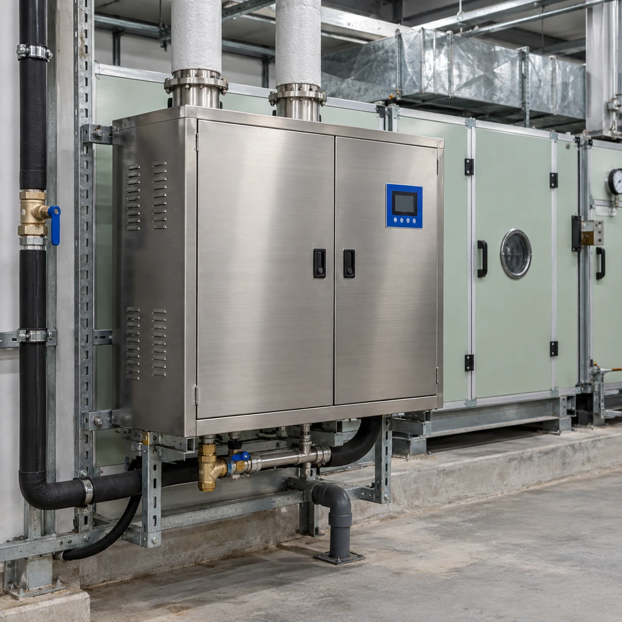
Steam Humidifiers
steam humidifier hvac
| Brand | shengtongJH |
|---|---|
| Steam generation | Industrial electrode or compatible resistive heating configuration |
| Electrode capacity classes | 23 / 45 / 90 kg/h |
| Heating power classes | Approximately 17.5 / 34.2 / 68.5 kW, respectively |
| Cabinet size, W × D × H (mm) | Approximately 430 × 300 × 650 / 530 × 365 × 720 / 890 × 365 × 720 by capacity class |
| Power supply | 380–400 V, three-phase; frequency and control supply matched to the destination |
| Steam distribution | Single lance, multi-tube manifold or engineered multiple distribution points |
| Control inputs | On/off, 0–10 V or other compatible proportional demand by controller selection |
| Plant interfaces | Remote enable, common alarm and operating indication; BMS gateway options |
| Air-side protections | Airflow proving and separate duct high-limit control |
| Water and drainage | Cylinder-compatible water feed, automatic drain and condensate management |
| Installation | Indoor plant-room cabinet or engineered protected enclosure |
Capacities and cabinet dimensions describe alternative equipment classes. Control protocol, distribution layout and electrical requirements are specified for the complete project; outdoor suitability is not assumed.
Steam capacity, cabinet arrangement, distribution manifolds, water treatment and BMS interfaces can be coordinated with your HVAC system and operating requirements.
Steam humidifier HVAC integration brings the generator, air-handling unit and humidity controls into one operating sequence. The aim is to deliver the required moisture at changing airflows while keeping ducts, filters and downstream equipment dry.
Generation, distribution, control
Size against the air that actually enters the system
An air-handling system may mix outdoor and return air, operate an economizer or change ventilation with occupancy. These modes change the moisture load. Selecting a humidifier from nominal room area alone overlooks the air that the system removes and replaces.
The design needs the entering-air condition, airflow range and target condition. Process moisture gains and recovery periods can also matter. Check both peak demand and the lower operating load, because a unit that cannot regulate sufficiently low may cycle or overshoot during mild conditions.
Absorption distance is an operating condition, not a fixed catalogue promise
Steam must become uniformly mixed with the air before it reaches surfaces that can collect moisture. Distributor geometry, entering-air temperature, existing humidity, air velocity and output all affect that distance. A multi-tube manifold can improve distribution where a single lance is unsuitable, but the choice still needs a calculation for the actual duct.
Filters, coils, elbows and sensors downstream impose their own positioning requirements. Provide the available clear duct section and intended airflow modes with the enquiry. Cabinet dimensions do not establish whether a complete humidification installation fits.
Constant-volume operation
A reasonably stable airflow simplifies matching steam rate to demand. Control can use a representative room or return-air measurement while maintaining an independent supply-duct limit.
Changes to fan speed, filters or balancing after commissioning can change the conditions at the distributor. Keep humidification within the air system's permitted operating range.
Variable-volume operation
At reduced airflow, the same steam output is added to less air. The plant sequence must limit output or inhibit operation when the available air cannot accept the demand.
Decide how fan state, airflow proof, damper positions and high-limit feedback affect the generator. A BMS percentage command without these relationships is an incomplete control strategy.
Give the BMS useful information without removing local protection
Remote enable, demand and common alarm signals can support plant operation. More detailed interfaces may expose service status, steam demand or fault information, depending on the selected controller. Name the required protocol and points in the equipment schedule rather than assuming every industrial cabinet supports every network.
Local water-level, overheating and air-side protections must still function when communication is lost or a remote command is incorrect. The control sequence should define the permitted response to a sensor, fan or network fault.
Different facilities need different evidence
Manufacturing
Relate the humidity target to the material or process. Airflow and maintenance must remain practical around the production schedule.
Laboratories
Coordinate moisture addition with exhaust and pressure relationships. A changing exhaust load can alter the humidification requirement.
Commercial facilities
Allow for occupancy, ventilation schedules and seasonal condensation limits. Control should follow the served zones rather than a single fixed calendar setting.
Make commissioning measurable
The installation team should establish that demand, airflow permission, high-limit action, drain operation and alarms behave as specified. Observe representative operating modes and record the final settings for maintenance. A generator producing steam is only one part of proving the system works.
For a smaller warm-air plant, see furnace supply-air integration. For boiling technology selection, compare the resistive hot steam configuration.
Steam capacity, cabinet arrangement, distribution manifolds, water treatment and BMS interfaces can be coordinated with your HVAC system and operating requirements.