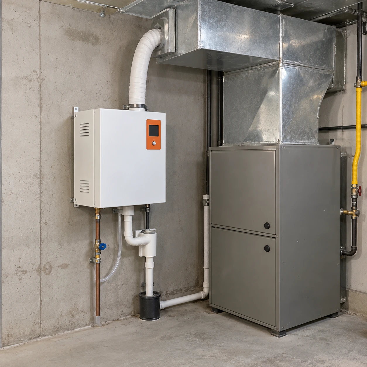
Steam Humidifiers
steam humidifier for furnace
| Brand | shengtongJH |
|---|---|
| Application interface | Supply-air duct of a compatible industrial or commercial warm-air unit |
| Steam output classes | 4 / 8 / 15 kg/h |
| Heating input | Approximately 3 / 6 / 11.3 kW |
| Electrical selections | 220–240 V single-phase for the compact class; 380–400 V three-phase for larger classes |
| Cabinet size, W × D × H (mm) | Compact: approximately 360 × 240 × 560; medium: approximately 430 × 300 × 650 |
| Steam outlet options | Nominal 22 mm compact / 34 mm medium connection classes; matching hose and distributor required |
| Inlet water pressure | 0.1–0.5 MPa configuration range; selected unit and local supply must match |
| Humidity demand | Return-air or representative space sensor; control interface matched to the air unit |
| Required interlocks | Proven airflow, duct humidity high limit and plant enable |
| Drain and mounting | Permanent drain; independent wall or rack mounting near the duct |
The furnace must be suitable for added humidity and the selected injection position. Connection sizes and cabinet classes are options; the approved equipment drawing defines the complete installation.
Steam output, supply voltage, distributor arrangement and furnace control interfaces can be configured for the warm-air installation.
A steam humidifier for furnace applications adds moisture to the supply air of a compatible warm-air system. The industrial steam generator has its own electrical heating source; it is connected to the air distribution, never to the combustion flue or directly into a process furnace.
Connect to the moving air, not the source of combustion
The word furnace can describe different equipment. Here the application is a warm-air heating unit with ductwork, such as a system serving a workshop or commercial facility. It does not mean adding steam to a kiln, melting furnace, combustion chamber or flue.
The generator boils water independently. The furnace fan transports the humidified air to the served area, so fan operation and distribution conditions still matter even though the steam does not depend on a wetted evaporative pad.
Installation position
Find a duct section where the steam can mix
The distributor needs enough suitable downstream space before the air meets an elbow, filter, coil or another obstruction. Temperature, humidity, velocity and steam rate affect absorption. A location that works during full heating airflow may be unsuitable at a lower fan speed.
Follow both the air-unit and humidifier installation requirements. Do not put the lance wherever a hole is easiest to cut. If the existing duct is too short, the response may be a different distributor or duct arrangement rather than a smaller hole or a longer hose.
Make humidification permission explicit
A humidity demand exists
A representative sensor calls for moisture. Its location should reflect the served area and avoid the immediate steam mixing zone.
The air path is available
The control sequence establishes the required fan and damper state. A proven airflow signal is stronger evidence than simply issuing a fan command.
The system remains within limits
A high-limit device and equipment protections can stop production if conditions become unsuitable. These protections must remain effective even when the main humidity demand continues.
Heating off does not always mean humidification off
Some installations allow a humidity call to run the distribution fan without a heat call. Others restrict humidification to defined heating modes. The correct choice depends on the air temperature, absorption conditions and unit controls.
An independent steam source does not automatically make every fan-only mode suitable. Define the allowed operating states before ordering the control interface.
Keep services outside the maintenance path
Position the generator so furnace panels, filters and burners remain accessible. Route steam, water and drain connections without blocking the equipment that will be serviced most often.
Steam hose should be supported and routed according to its instructions. Low spots can collect condensate and cause unstable delivery; a longer hose is not automatically a workable relocation solution.
What to provide for a compatible supply package
Include the warm-air unit identity, supply-duct dimensions, airflow modes, available straight length, voltage and intended humidity control. Photos can show space constraints, while the air-unit documentation establishes what its controls and construction permit.
For replacing an existing installation, the furnace steam humidifier retrofit page explains which existing parts need to be checked instead of automatically reused.
Steam output, supply voltage, distributor arrangement and furnace control interfaces can be configured for the warm-air installation.