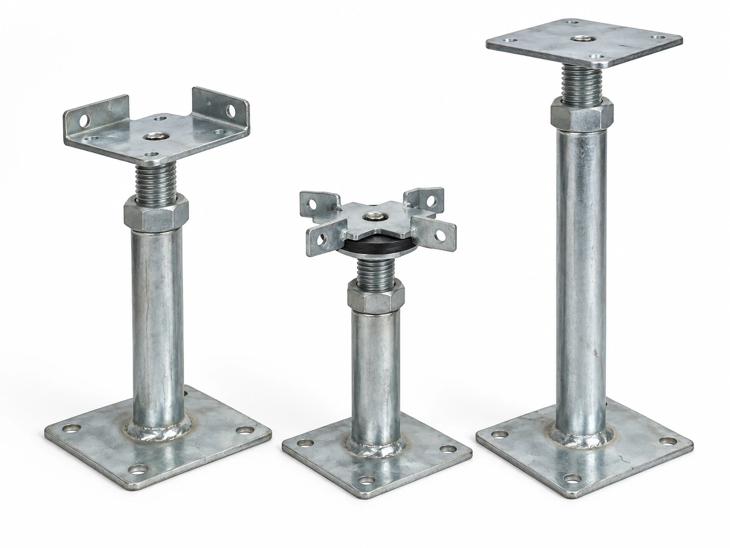
Raised Floor Pedestals
raised floor pedestals
| Brand | shengtongjh |
|---|---|
| Construction | Zinc-plated steel head and base assemblies; matched gaskets, locking parts and stringer connections |
| Cross-head plate options (mm) | Head: 71 × 71 × 3; paired base: 100 × 100 × 2. Values are plan width × depth × plate thickness. |
| Stringer-grid plate options (mm) | Head: 75 × 75 × 3; paired base: 95 × 95 × 2. Values are plan width × depth × plate thickness. |
| Leveling provision (mm) | 50 mm adjustment travel in selected threaded assemblies; nominal support height specified separately |
| Installation interfaces | Panel-bearing head, perimeter support and base fixing selected as parts of the complete floor system |
Head and base dimensions describe separate paired configurations, not interchangeable parts. Plate thickness is not pedestal height. Floor load capacity depends on the complete assembly, support layout and installation.
Pedestal height, head arrangement and connection provisions can be customized to the panel system and site conditions.
Raised floor pedestals carry access-floor panels above the structural slab, creating space for services while supporting a usable floor surface. The head, vertical support, base and associated stringers must work with the chosen panels and installation layout.
Follow the support from panel to slab
The head locates the floor
The upper plate provides bearing for the panel or a connection for the supporting stringers. Its shape, fixing holes and locating features must match the panel arrangement. A head that looks similar can still leave a panel corner incorrectly seated.
The upright establishes the level
The stem and tube bridge the service void. A compatible adjustment and locking arrangement allows the heads to form a consistent plane above an uneven structural floor. The required extension must remain within the limits of that assembly.
The base transfers the reaction
The base plate bears on the prepared substrate and works with the specified fixing method. Its performance depends on contact, substrate condition and installation quality as well as the steel component itself.
Match the head to the support arrangement
In a suitable pedestal-supported system, panel corners locate directly on the heads. A stringer-grid system adds horizontal members between supports, with the panel edges and connections coordinated around that grid. Neither arrangement can be selected solely by the appearance of the pedestal.
Check how the panel is located, whether it is secured or freely removable, and how its underside meets the gasket or bearing surface. Confirm stringer-end details at the same time. Similar nominal panel dimensions do not establish compatibility between components from different floor systems.
Describe the space you need below the floor
The finished walking surface, the pedestal bearing level and the clear service void are different references. Panel thickness and the supporting members occupy part of the total floor build-up. A specified finished-floor height therefore cannot be used directly as a bare pedestal height.
Coordinate service routes with bases and uprights before ordering. A pipe or cable tray that occupies a planned support position can require a designed bridging detail. Moving the pedestal aside without reviewing the panel support changes the structural arrangement.
Detail edges and openings as separate conditions
A regular interior grid repeats across an unobstructed area, but walls, columns, doorways and service openings interrupt that pattern. A perimeter head may need a different bearing shape or gasket so it can support the cut edge without projecting into the wall. Door transitions also need the support level to agree with the adjacent floor.
Cut panels require their own support detail. The published behavior of a complete panel should not be assumed for a narrowed strip or a panel with a large opening. Extra pedestals, profiles or other approved supports may be required. Provide the opening and perimeter layout with the panel schedule so these pieces are included in the package.
A pedestal load is not a floor-system rating
A vertical test on an individual support answers a different question from a point load on a panel or a rolling load moving across joints. Floor behavior also involves the head connection, stringers, panel span, base restraint and installed height. Higher supports can change the need for horizontal restraint and bracing.
Specify the actual equipment and movement conditions for the complete floor design. Do not convert a pedestal's axial test value into a permissible equipment weight or assume a larger base plate establishes seismic performance. shengtongjh coordinates component selection around the documented system requirements.
Identify replacement parts before removing support
For an existing floor, record the panel underside, head and gasket arrangement, stringer connection, installed height and base condition. An old part's overall height alone is insufficient. A replacement should restore its intended support and access function without forcing the surrounding panels into a new position.
Keep service access in the plan: panel lifting should not depend on dismantling the supporting grid. Investigate loose bases or rocking panels through the floor system's maintenance procedure, with the affected area unloaded as required. For height selection, see adjustable raised floor pedestals; for electrical connection requirements, review grounding raised floor pedestals. Request a matched pedestal configuration.
Pedestal height, head arrangement and connection provisions can be customized to the panel system and site conditions.