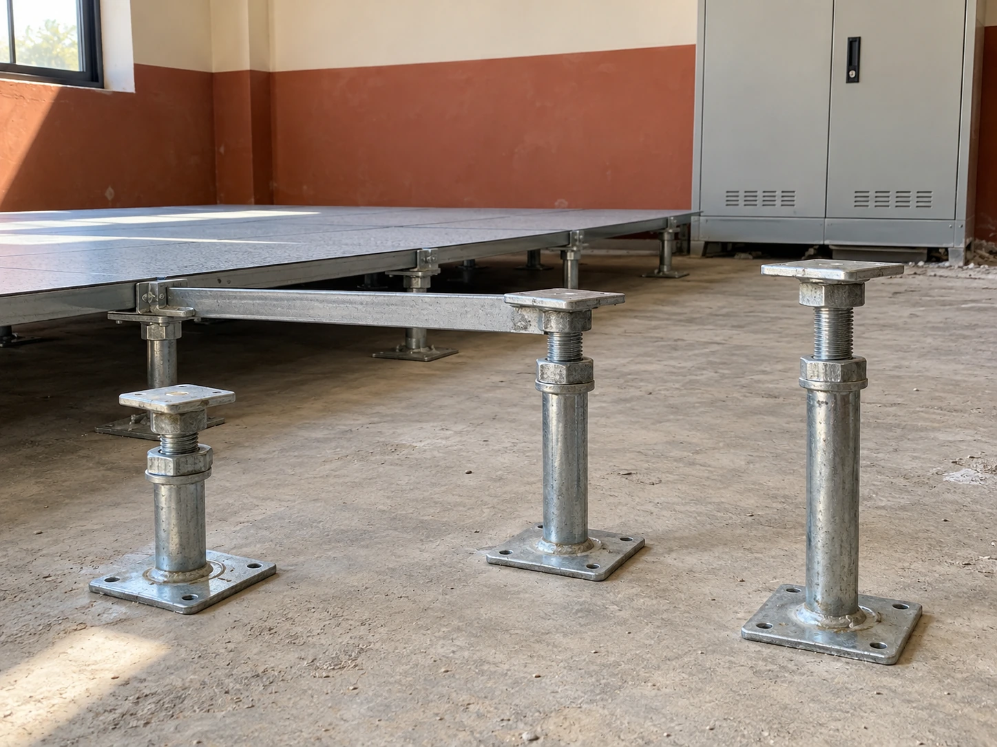
Raised Floor Pedestals
adjustable raised floor pedestals
| Brand | shengtongjh |
|---|---|
| Pedestal adjustment-height bands (mm) | 63–94; 80–130; 120–200; 170–290. Separate assembly sizes in an M16 screw-pedestal arrangement. |
| Thread and tube option (mm) | M16 screw arrangement with a tube outer diameter of 22 and wall thickness of 1.8 |
| Material and surface | Galvanized steel; coating and contact components selected for the indoor installation |
| Head and locking arrangement | Panel-compatible head and gasket; locking components and method matched to the selected pedestal assembly |
| Base installation | System-specified adhesive or mechanical fixing detail, coordinated with the substrate and structural requirements |
Height bands apply to different pedestal assemblies, not one universal travel range. Establish the finished-floor level from the selected panel, finish and head-interface build-up. Minimum engagement and installation limits come from the matched assembly.
Height selection, head details and base-fixing provisions can be customized to the floor layout and substrate conditions.
Adjustable raised floor pedestals compensate for differences in the structural slab so the supported floor can reach a consistent level. The useful adjustment range must suit the highest and lowest substrate positions while preserving the required engagement and locking arrangement.
Begin with one finished-floor datum
The support setting should come from the level the completed floor must reach. Agree that datum at door thresholds, adjacent surfaces and equipment interfaces, then account for the panel and finish above the pedestal. Setting every bare support to the required walking-surface height would place the assembled floor too high.
Survey the slab across the area, including local high spots and depressions. A room can require several support lengths even though its finished floor is level. Selecting from an average slab measurement can leave the shortest positions unable to lower far enough and the deepest positions beyond the permitted extension.
Separate the height band from the adjustment travel
A pedestal family can cover a broad range of floor heights through several body and stem combinations. That does not mean one individual support extends across the whole family range. Choose an assembly whose allowed height band contains the required setting, including the adjustment needed for actual slab variation.
Keep adequate engagement between the threaded and receiving parts. The visible length of thread is not an invitation to keep extending it: usable engagement, locking and structural limits belong to the selected assembly. If a support cannot reach the required level within those limits, a different size or approved support detail is needed.
Plan around both directions of adjustment. A support ordered near the top of its range may have little allowance for a deeper local slab, while one near its lowest setting may not accommodate a high spot. Where conditions change across the room, identify the different assembly groups on the layout.
Keep alignment, bearing and locking connected
- Establish the grid. Head positions must agree with the selected panels and stringer connections, including perimeter conditions.
- Set the bearing plane. Check the installed panel and support relationship against the common datum, rather than judging each head in isolation.
- Secure the setting. Use the locking method specified for the assembly after the correct position is established.
- Check the adjoining bays. A local change can affect panel seating, joint alignment and the fit of neighboring stringers.
Different mechanisms use different locking details. A lock nut, locking screw and a specified thread-locking compound are not interchangeable instructions. Installation should follow the supplied floor-system method, including base preparation and curing requirements where adhesive is used.
When a panel rocks
Check more than the support height. Debris at a bearing point, a displaced gasket, the wrong panel position or a damaged component can create movement. Turning a nut to compensate for another fault may leave the neighboring panel incorrectly supported.
Inspect the panel-to-head contact and the surrounding grid before deciding on an adjustment. The aim is proper seating across the intended supports, with the required joint alignment and floor level maintained.
When the base moves
A loose or poorly seated base is a different problem from a height-setting error. Increasing stem extension does not repair the connection to the slab. Review the substrate and the specified fixing method before returning the affected area to service.
Unspecified packers or improvised wedges can change bearing and restraint. Any leveling or repair component should belong to an approved detail for that installation, rather than becoming an unrecorded addition below the base.
Order support lengths with the floor layout
Provide the finished-floor datum, slab level range, panel build-up and location of thresholds or service obstructions. Include whether the system uses stringers and identify any perimeter or equipment-support detail. This allows the height bands and quantities to be assigned to the actual work instead of choosing one nominal length for every position.
For replacement work, retain the existing head and panel interface information as well as the height measurements. The broader raised floor pedestal selection covers those mechanical interfaces. Send the layout to shengtongjh for a configuration quotation.
Height selection, head details and base-fixing provisions can be customized to the floor layout and substrate conditions.