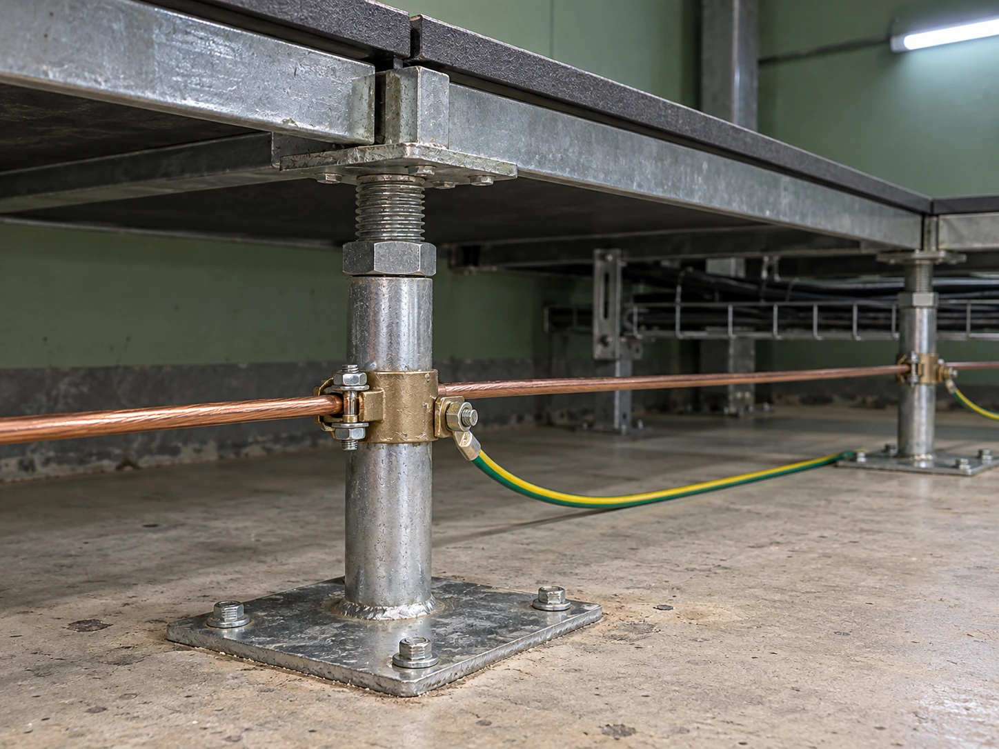
Raised Floor Pedestals
grounding raised floor pedestals
| Brand | shengtongjh |
|---|---|
| Support height options (mm) | M16 screw assemblies: 120–200 or 170–290; M20 socket assembly: 225–285. Separate size options. |
| Round-post geometry (mm) | M16 arrangement: 22 outer diameter × 1.8 wall; M20 arrangement: 24 outer diameter × 2 wall. Clamp fit must match the actual post. |
| Mechanical construction | Galvanized steel head, stem and base; panel and stringer interfaces selected for the floor system |
| Bonding connection | Purpose-designed pedestal clamp or documented integral terminal; conductor and connector selected together under the electrical design |
| Verification scope | Connection continuity and bonding records; floor-surface and personnel ESD performance assessed separately where required |
Height options are pedestal assembly bands, not finished-floor heights. Conductor area, clamp rating, connection spacing and test acceptance values are project-specific. Mechanical fixing to the slab is not evidence of an approved electrical connection.
Pedestal geometry and bonding connection provisions can be customized to the floor arrangement and approved electrical design.
When specifying grounding raised floor pedestals, the task is to connect the metal supports into the installation's designed bonding network. The support geometry, connection hardware and electrical path need to be coordinated; a metal pedestal alone does not establish a complete grounding or static-control system.
Specify a connection path, not just a metal support
A raised-floor support can be part of a bonded metal structure, but the path must be intentional. Identify which components are connected, the designated bonding network and the means of maintaining those connections. A pedestal attached to concrete should not be treated as an earth electrode merely because its base is fixed to the slab.
The electrical design also needs to account for the boundaries between supports, stringers, panels and other equipment. Do not assume every joint carries current reliably through pressure or incidental contact. The floor structure does not automatically replace the protective conductors required by equipment and its electrical installation.
Review three interfaces in the bonding assembly
Post to clamp
Select for the actual post shape, outer dimension, material and surface finish. A fitting made for a round post may not seat correctly on a square tube, and a near match is not proof of compatibility. The connection must not interfere with the pedestal's leveling or structural functions.
Clamp to conductor
The connector must accommodate the specified conductor material, construction and size. Its conductor saddle and hardware have a defined purpose. A general cable-support clip should not be assumed to perform as a bonding connector simply because both attach to the same pedestal.
Conductor to the designed network
Route the connection to the identified bonding arrangement in the electrical design. Preserve the specified network across service routes and floor sections. A wire connected to a pedestal but ending at an arbitrary metal object does not establish the intended path.
Preserve the contact interface
Coatings, corrosion and contamination can affect an electrical joint. Use the connector manufacturer's approved contact method and compatible materials. Do not assume that scraping off a protective finish or adding an ordinary washer reproduces a purpose-designed connection.
Installation details, including tightening and any surface preparation, belong to the selected connector. A conductor wrapped around an adjustment thread is difficult to control and can obstruct later leveling. Use the documented attachment provision, leaving the support mechanism serviceable.
Keep the connection accessible
Position connections so inspection and maintenance can take place through the intended floor access. Avoid routing that catches on lifted panels, crosses a moving adjustment part or becomes trapped beneath a panel edge. Coordinate nearby cable trays without using the bonding lead as a mechanical restraint.
If the floor is altered, review the affected connections as part of the work. A removed support, relocated tray or replacement component can change the intended path. Record the final arrangement so the next maintenance team can identify it.
Understructure bonding does not establish ESD floor performance
An electrically connected pedestal network answers a different question from the resistance of the finished floor surface. Panels, coverings, adhesives and their contact arrangements can influence the route from that surface to the designated grounding point. A successful check at a metal clamp does not prove the performance of the complete surface.
Where the floor is intended to ground personnel, footwear and the person-floor contact must also be evaluated as a system. Floor and footwear labels alone are insufficient. The same distinction matters at ESD workbenches, where the work surface and personnel grounding arrangements have their own defined connections.
Include verification and maintenance in the supply scope
Agree the connection layout, hardware identification, installation instructions and required verification records with the responsible electrical professional. The applicable requirements depend on the building and location. Do not substitute an arbitrary resistance target or universal connection spacing for the approved design.
For procurement, provide the pedestal drawings, post dimensions and finish, conductor specification, access constraints and relevant floor-system details. State whether the request is for bare supports, supports with connection provisions or a coordinated hardware package. Mechanical selection remains covered under raised floor pedestals. Ask shengtongjh to coordinate the pedestal and connection requirements.
Pedestal geometry and bonding connection provisions can be customized to the floor arrangement and approved electrical design.