Fan Filter Units & Air Terminals
FFU Control Systems
| Control scope | Individual FFUs, room groups or process zones; network capacity matched to the selected controllers |
|---|---|
| 7-inch operator panel | Body W × D × H: 200.3 × 34 × 146.3 mm; mounting cutout W × H: 192 × 138 mm |
| 10.1-inch operator panel | Body W × D × H: 271 × 36.4 × 213 mm; mounting cutout W × H: 260 × 202 mm |
| FFU control interface | 0–10 V analog or RS-485 / Modbus RTU through compatible fan controllers |
| Building system connection | Modbus TCP or BACnet through a matched controller or gateway and agreed point list |
| Status and alarms | Run state, communication and fan faults; RPM or filter pressure where supported by the selected equipment |
| Operator panel supply | 24 VDC; field controller and fan power supplies selected separately |
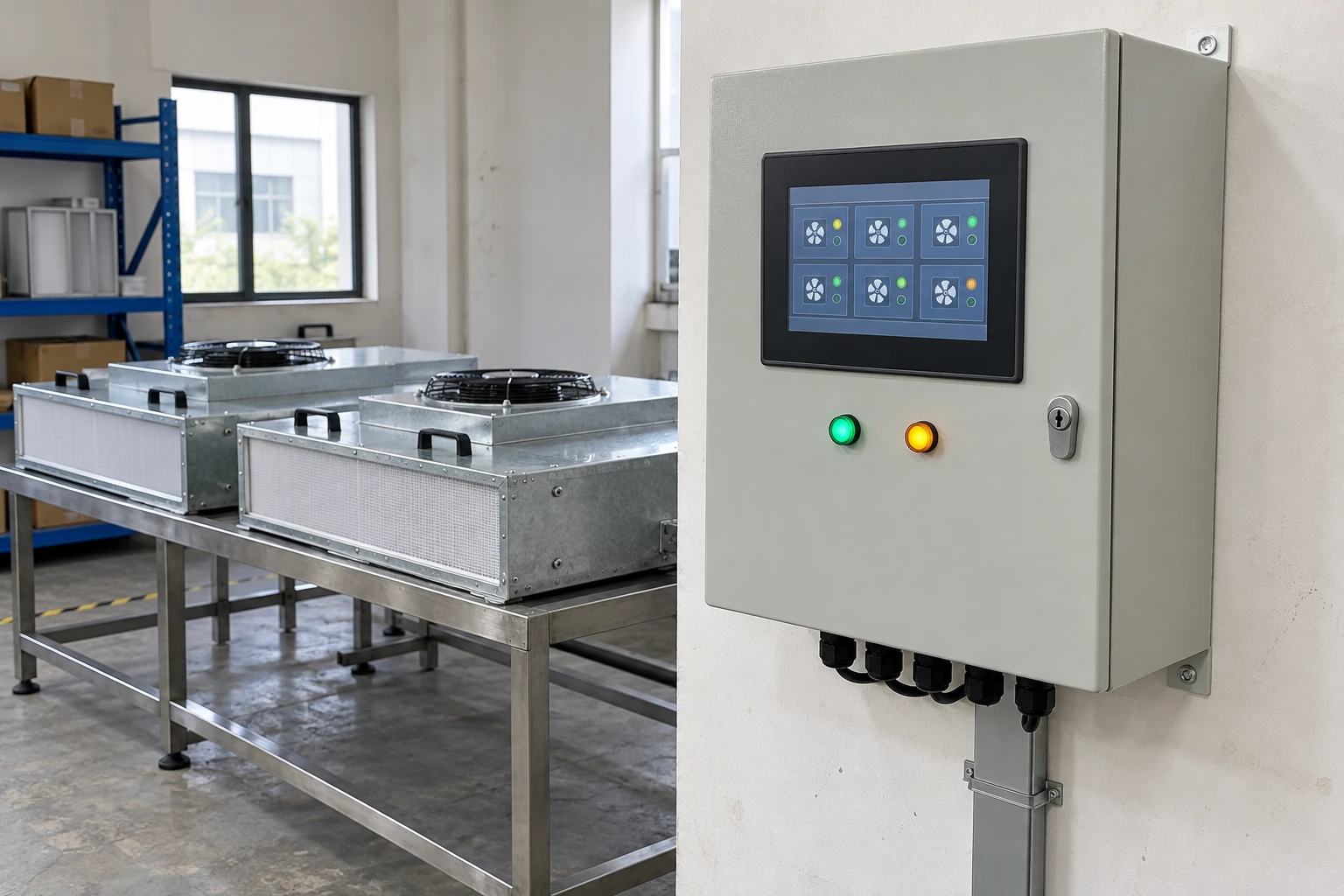
| Enclosure | Wall mounted steel cabinet; internal layout, cable entry and service space matched to the installation |
Panel dimensions describe the touchscreen body and cutout, not the complete cabinet. Motor compatibility, feedback functions and cabinet dimensions depend on the selected configuration.
The panel arrangement, FFU grouping, control interfaces and enclosure can be configured for your operating environment and installation requirements.
FFU Control Systems coordinate fan filter units serving production rooms, inspection stations and local clean air enclosures. A useful system gives operators a clear view of each unit, applies the right settings to each zone and helps maintenance staff locate faults without repeatedly accessing ceiling equipment. The control package must connect compatible motors, field controllers, communications and an operator interface.
Build the control path around the installed fans
Motor and field controller
The motor type and its control input determine which commands can be used. An EC motor may accept an analog signal or communicate through a matched controller. A different motor or drive can require a different arrangement; a common connector shape does not establish compatibility.
Network and interfaces
The network carries commands and available feedback. Protocol, device addressing and the meaning of each data point must agree across the connected equipment. A gateway can connect different systems only when the required points and command behavior are explicitly mapped.
Panel and zone display
The touchscreen presents unit locations, operating modes and alarms. Fan power distribution remains a separate electrical function. Selecting a larger display does not increase motor compatibility or the number of devices a communication segment can support.
Shared demand or individual control?
An analog arrangement suits a small group that can follow a common speed demand. It can keep operation straightforward, but the demand signal alone provides little information about the condition of each fan. Separate feedback is needed where individual fault identification matters.
An addressable network supports individual settings and diagnostics within room groups. It is useful where equipment positions, filters or process loads differ. Its value depends on an accurate unit map and compatible controllers, with segment capacity and cable layout established for the actual installation.
Make the unit map usable at ceiling level
Give every FFU a unique identity linked to its physical position. Grouping should follow the room or process served, while retaining individual adjustment for balancing. When a controller is replaced, its address and saved settings must be restored against that map so that the display continues to identify the correct fan.
For the equipment being controlled, see the fan filter unit page. The control system should be selected alongside the fan and filter configuration.
Display what has actually been measured
- Requested output
- A percentage or speed command describes the instruction sent to a controller.
- Motor feedback
- Reported RPM indicates rotation where the motor or controller provides that feedback. It does not establish delivered airflow.
- Airflow or pressure
- These require appropriate measurement hardware and defined measurement locations. Closed loop airflow control requires supported feedback and a suitable control function.
Filter pressure can help track loading under comparable operating conditions. It does not verify filter integrity or room cleanliness. Airflow should be measured during commissioning rather than inferred from the screen.
Turn alarms into maintenance actions
A communication alarm means the controller cannot obtain a reliable response; it does not by itself prove the fan has stopped. A fan fault, a pressure threshold and a maintenance reminder describe different conditions and should remain distinguishable.
Useful alarm records identify the affected unit, the event time and the condition detected. Acknowledgment records that somebody has seen the event; it does not correct the fault. Maintenance staff can then check the relevant controller, fan or sensor without treating every alarm as a filter replacement request.
Commission the interfaces as well as the fans
- Reconcile the unit schedule. Match each device identity to its ceiling location, room group and motor interface before applying grouped commands.
- Prove command and feedback paths. Check approved local, panel and building system modes, then controlled communication loss and power restoration under a safe commissioning plan.
- Record the operating result. Measure airflow, retain the accepted settings and deliver the unit map, network schedule, point list and configuration backup.
For a quotation, provide the FFU quantity by zone, motor and controller details, required building system connection and preferred panel location. State whether the scope includes only controls or also fan power distribution, sensors and commissioning support. This defines a complete interface responsibility for the installation.
The panel arrangement, FFU grouping, control interfaces and enclosure can be configured for your operating environment and installation requirements.