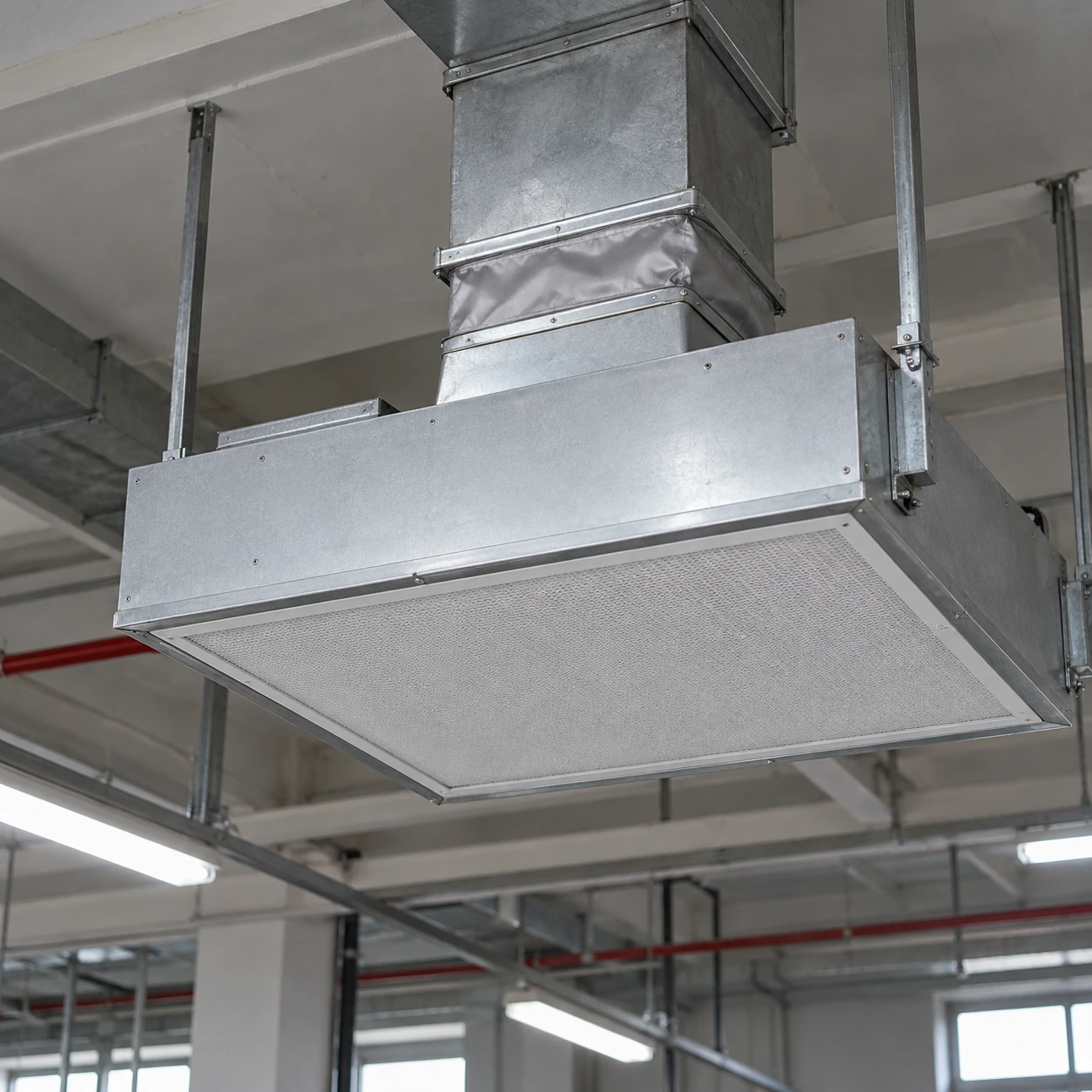
Fan Filter Units & Air Terminals
ffu in hvac
| Brand | shengtongJH |
|---|---|
| System role | Local final-filter supply within a coordinated HVAC design |
| Housing W × D × H options | 575 × 575 × 280 / 1175 × 575 × 280 mm |
| Matched filters W × D × H | 570 × 570 × 70 / 1170 × 570 × 70 mm |
| Filter options | H13 or H14 HEPA according to the protected process |
| Fan arrangement | Adjustable AC or EC centrifugal drive |
| Electrical supply | 220–240 V, 50 Hz; other supply by selected equipment |
| Inlet alternatives | Return plenum or engineered duct connection |
| Housing | Galvanized steel; stainless steel where appropriate |
| Control coordination | Local/group run command; building-control interface by specification |
| Pressure selection | Fan duty includes filter and connected air-path resistance |
| Thermal provision | Cooling and humidity control provided by coordinated HVAC equipment |
A duct connection changes the operating pressure condition. Cooling, ventilation and room-pressure duties require separate design values and cannot be inferred from FFU airflow alone.
Inlet interfaces, controller signals, enclosure sizes and final-filter selections can be customized to the HVAC arrangement.
An FFU in HVAC adds powered final particle filtration near the area being served. It must be coordinated with the building air system because recirculation, outdoor air, thermal loads and pressure control are different duties.
Assign each part of the system its job
A central air-handling system may condition outdoor air and remove room heat, while ceiling FFUs recirculate air through final filters near the process. This division can provide local particle-control flexibility, but the airflow figures describe different functions. Recirculated air does not count as new outdoor ventilation air.
Where exhaust removes air from the building, a coordinated make-up supply is still needed. Increasing recirculation alone cannot replace the exhausted volume. Room pressure depends on the balance of supply, return, exhaust and leakage paths, including doors in their normal operating states.
Account for heat and moisture
People, production equipment, lighting and fan operation contribute to the thermal load. The FFU does not remove that heat simply because its supply feels like moving air. Coordinate cooling capacity with the actual load and required temperature.
Humidity control also remains a conditioning duty. Moisture from outdoor air or the process needs an appropriate treatment strategy. Avoid conditions that allow condensation on cold surfaces near filters and electrical equipment.
Do not let two controls fight each other
A duct-fed FFU and an upstream airflow-control device can influence the same flow. Their operating ranges and control sequence need coordination. An upstream pressure change can move the FFU away from its intended duty even though its local setting is unchanged.
Agree which controller maintains which variable and what happens when either system stops. Include the required run permissions and fault responses in the equipment selection.
Is an FFU a replacement for a supply diffuser?
Not automatically. A diffuser distributes air supplied by another fan, whereas an FFU introduces its own powered stage and final-filter resistance. Replacing one with the other changes support, electrical, pressure and maintenance requirements. Use the FFU where the process needs that local filtration duty.
Check the complete operating condition
Assess the installation with neighbouring supply and exhaust equipment running as intended. Confirm useful airflow, room pressure and the relevant temperature and humidity conditions separately. This makes it possible to identify which subsystem needs adjustment instead of attempting to correct every issue with the FFU speed control.
Inlet interfaces, controller signals, enclosure sizes and final-filter selections can be customized to the HVAC arrangement.