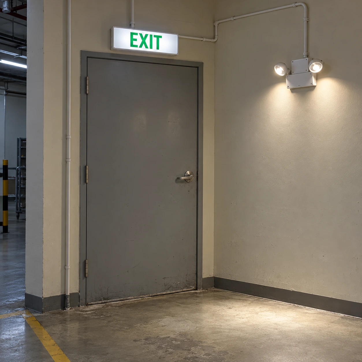
Emergency Lighting
exit emergency lighting
| Box sign body, W × H × D (mm) | Approximately 330 × 191 × 54 |
|---|---|
| Compact sign/light combo, W × H × D (mm) | Approximately 349 × 221 × 54 |
| Separate emergency unit sizes, W × H × D (mm) | Approximately 181 × 121 × 67; 260 × 121 × 67 |
| Face and mounting | Single/double face; wall, ceiling or end mounting according to the selected fixture |
| Power choices | Self-contained battery version or compatible central emergency supply |
| Sign and light selection | Lettering/pictogram, direction, enclosure and emergency photometry matched to the location |
Sign body dimensions do not establish viewing distance. Separate luminaires or combination heads are selected using emergency-mode light distribution and the final mounting arrangement.
Exit signs, route luminaires and supply interfaces can be customized to the approved building layout.
Exit emergency lighting helps people identify an exit and see how to reach it. This usually involves both sign visibility and usable light along the route, with equipment arranged for the directions people approach from rather than only the view directly in front of a door.
Start from the occupant's approach
A sign directly above a door can be clear from one position and hidden from another. Ceiling beams, storage, open doors and changes in corridor direction affect the view. Follow the intended escape route from the occupied area and identify the decision points where a person needs to recognise the next direction.
This approach also identifies places that need illumination even though no sign belongs there. A turn, threshold, stair tread or change in level can be difficult to negotiate in darkness. The sign directs movement; the emergency luminaires make the route usable.
Keep identification and illumination distinct
| Question | Exit identification | Route illumination |
|---|---|---|
| What does the equipment provide? | A visible exit message or approved directional symbol. | Light on the walking surface and relevant changes in level. |
| What affects placement? | Approach directions, sight lines, obstructions and the sign format. | Mounting height, optical distribution, aiming and the actual route geometry. |
| What needs a separate check? | Face visibility and correct direction through the required operating conditions. | Emergency-mode light levels and continuity along the required route. |
A glowing exit face should not be treated as the primary floor light unless the complete equipment has a documented lighting function and the installation meets the design. A combination unit adds dedicated heads for that purpose; an ordinary sign face does not automatically do the same job.
Carry the route beyond the first door
An exit may lead into a stair enclosure, passage or external discharge area rather than directly to an open safe area. The lighting design should follow the required route through those transitions. An interior unit's environment rating may not suit an exposed landing, and a sign inside a doorway may be difficult to see from an adjoining passage.
Use equipment appropriate to each location and the applicable design requirements. A separate luminaire can illuminate a landing while a sign is positioned for the approach. The final escape-door hardware and clear opening remain separate building considerations; an illuminated sign does not establish that the door itself provides a suitable means of egress.
Supply the right failure response
Self-contained equipment carries its own battery, while central arrangements supply compatible signs and luminaires from a common source. Either approach requires the relevant normal lighting failure to be detected. The normal control state must not prevent the required emergency response.
The required duration and transfer behaviour belong to the project and equipment selection. They are not established by the sign's size, colour or the presence of an LED.
Keep signs consistent after changes
Partitions, racks and door-use changes can make old directions misleading. Update the affected sign scheme and lighting together when the approved route changes. A replacement sign should match the specified face, direction and viewing arrangement, not simply cover the old fixing holes.
During maintenance, observe both the sign and nearby illumination under the planned test condition. Record problems with visibility, output and duration as distinct issues.
Select a coordinated package
For procurement, pair the route plan with sign-face requirements, mounting positions, supply arrangements and emergency photometry. This reduces the chance of obtaining compatible electrical parts that serve incompatible locations. Compare combined exit signs and light heads where a shared position works, or use separate emergency units where the optics need more freedom. Final placement and approval remain part of the responsible building and electrical design.
Exit signs, route luminaires and supply interfaces can be customized to the approved building layout.