Emergency Lighting
emergency lighting units
| Compact overall sizes, approximately W × H × D (mm) | 181 × 121 × 67; 260 × 121 × 67 |
|---|---|
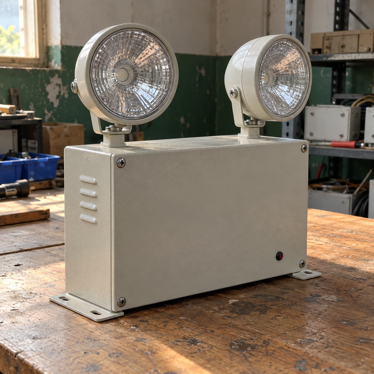
| Construction choices | Moulded enclosure or steel housing; two adjustable LED heads |
| AC input | 120–277 V AC, 50/60 Hz configuration |
| Battery arrangement | Integral rechargeable battery matched to the unit charger |
| Load arrangement | Integral heads; remote-head support only on a rated compatible version |
| Test access | Local test button/status indicator; self-test option |
Housing material and head geometry depend on the selected unit. Allow for head adjustment and cover removal beyond the stated compact dimensions.
Housing, lamp-head arrangement, mounting and test options can be customized for the installation and service routine.
Emergency lighting units bring the charger, battery, changeover function and lamps together in one serviceable assembly. They can be practical for isolated rooms, local additions or facilities where running a new central emergency circuit would be disruptive.
A complete local assembly with a defined load
A self-contained emergency lighting unit is often selected because its operating boundary is easy to understand: normal power charges a battery, and the battery supplies the unit's lamps when the monitored supply fails. This can make a small addition simpler than extending a central system. It also gives the maintenance team a discrete item to identify, test and replace.
The load boundary still matters. Some versions supply only their own heads, while others have a documented allowance for compatible remote lamps. A spare connector or an apparently larger battery does not establish remote capacity. Added heads change the total load and can shorten the available duration unless the assembly was selected for them.
Match the housing to the location
A compact moulded unit can suit a protected indoor corridor. A steel enclosure may be preferable where mechanical damage is a concern, but material alone does not establish impact or environmental protection. Loading bays, wash areas, refrigerated spaces and outdoor exits need equipment with appropriate documented conditions of use.
Battery performance can be particularly sensitive to temperature. A unit mounted high in a warm plant room experiences different conditions from one beside a cold-store doorway. Selecting a fixture by room label alone misses those local conditions. Position it where its approved operating range and service access can both be maintained.
Leave room to aim the heads
Adjustable heads need a clear field of view toward the route. A nearby beam, sign or pipe can block the light even when the housing fits neatly. The final envelope includes the rotated heads, not just the charging box. Secure the adjustment after aiming so ordinary cleaning or maintenance does not change the distribution.
A higher mounting position does not automatically increase useful coverage. Wider spacing can leave weak areas between beams, while a steeply aimed head can concentrate light in a small patch. Use the fixture's emergency photometry for the actual geometry.
Leave room to service the unit
The cover, battery connector and test facilities must remain accessible. A unit above storage racks may be easy to install before the racks arrive but difficult to maintain later. Consider ladder access, equipment isolation and cover removal when choosing the position.
Record the battery assembly and replacement method. A different battery with the same nominal voltage can have unsuitable charging requirements or fail to provide the documented duty.
Replace the cause of a fault
| Observed behaviour | Questions for maintenance |
|---|---|
| Unit never starts in a planned test | Is the correct normal circuit monitored, is the battery connected and charged, and is the test being performed according to the instructions? |
| Lamps start but fade or stop early | Is the battery at full charge, is it degraded, and has an additional load been connected? |
| Unit runs but the route is poorly lit | Have head positions, obstructions, mounting conditions or the room layout changed? |
| Repeated fault indication after replacement | Does the new component match the charger and control system, and has the underlying supply or temperature problem been corrected? |
Build a replacement schedule that stays usable
Keep the unit location, circuit identity, head type and battery information together. Where a building has several generations of equipment, group the maintenance work by actual assembly rather than appearance. Two similar white boxes may use different batteries or have different remote-load limits.
For a doorway where sign identification and nearby illumination can share a suitable position, compare exit lights with emergency lighting. A combination unit reduces separate enclosures, but its shared battery and lamp load still need to be evaluated as a complete assembly.
Housing, lamp-head arrangement, mounting and test options can be customized for the installation and service routine.