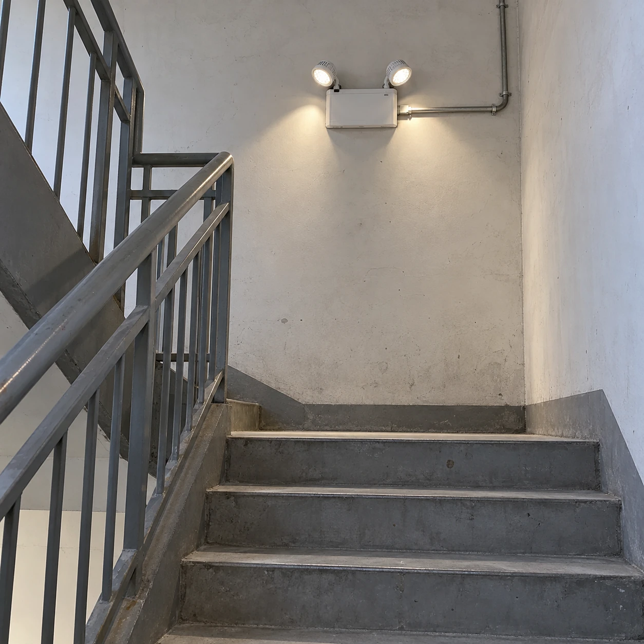
Emergency Lighting
commercial emergency lighting
| Local unit sizes, approximately W × H × D (mm) | 181 × 121 × 67; 260 × 121 × 67 |
|---|---|
| Project arrangements | Local battery units; approved emergency conversions; central emergency supply |
| Input for compact units | 120–277 V AC, 50/60 Hz |
| Installation choices | Wall or ceiling; directional heads selected for the mounting height and route |
| Monitoring | Individual indicators or compatible automatic test/reporting equipment |
| Environmental selection | Indoor dry-area units; damp, wet or cold-location versions selected separately |
Fixture spacing is determined from emergency-mode photometry and the actual layout. Cabinet dimensions or a claimed maximum spacing do not establish coverage for a building.
The fixture mix, supply arrangement and test access can be customized for the building zones and operating schedule.
Commercial emergency lighting has to remain useful while a building changes around it. New shelving, a subdivided tenancy, revised opening hours or an altered escape route can turn a previously suitable arrangement into an incomplete one without changing any lamp.
Organise the lighting around building zones
A commercial building may contain offices, stock rooms, loading areas and shared stairs, each with a different pattern of use. The emergency arrangement should follow the approved escape routes across those boundaries. Responsibility can become unclear where a tenant controls one part of the normal lighting and the building operator maintains another.
| Building condition | Common difficulty | Design response |
|---|---|---|
| Warehouse or stock room | Racks and goods interrupt an originally open light path. | Evaluate the finished storage layout and the route at floor level. |
| Office or tenancy subdivision | New partitions alter both visibility and local supply zones. | Review signs, emergency luminaires and failure detection with the revised layout. |
| Shared stair and landing | Changes in direction and level need useful illumination from several positions. | Use appropriate optics and locations for the stair geometry. |
| Loading or external discharge area | Moisture, temperature and vehicle activity affect equipment and access. | Select the environmental construction and mounting around the real exposure. |
Coordinate with energy-saving controls
Occupancy sensors, time schedules and dimming reduce normal lighting use. Emergency operation needs a defined response when normal power is lost, including when a room was already switched off or dimmed. Supplying an ordinary controlled circuit from an inverter does not by itself prove that every required light will turn on.
Identify the normal-power sensing point and the required override behaviour for each zone. An appropriate control device can allow normal energy-saving operation while establishing the required emergency state. The chosen device, source and luminaire need compatible instructions; a generic relay description is insufficient to define the installed system.
Upgrade in phases without losing the route
A phased refurbishment can leave old battery units, new LED conversions and a central supply operating together. Mark which areas and circuits belong to each phase. Before removing a fixture, establish how the occupied route remains served during the work. Temporary arrangements and testing should be coordinated with the facility's responsible personnel and project requirements.
Replacement lighting can change beam shape even where the new unit uses less power. Compare the emergency distribution and the finished mounting position. Existing holes, conduit and sign locations are useful constraints, but they should not dictate a replacement that leaves part of the route poorly illuminated.
Decentralised batteries
Local units can make a small modification manageable without extending a central emergency circuit. They also distribute battery replacement work around the building. The operational cost includes access equipment, fault finding and repeat visits, not only the replacement battery.
Central equipment
A central arrangement can concentrate maintenance and supervision. It requires suitable outgoing circuits, local failure response and a service plan for the central source. A single accessible cabinet is useful only if the consequences of a circuit or source fault have been addressed.
Make the handover useful to the facilities team
Provide a location schedule, circuit references, test method, fault indications and replacement information. Record who reviews automated test results and who closes out a fault. A dashboard that nobody checks does not resolve a failed battery or blocked beam.
After significant changes in storage, partitions or access routes, review the affected lighting. Keep the accepted layout and emergency photometry available for that decision. Local emergency lighting units and LED emergency arrangements provide different ways to implement the design; the appropriate mix follows the building's operation and maintenance capability.
The fixture mix, supply arrangement and test access can be customized for the building zones and operating schedule.