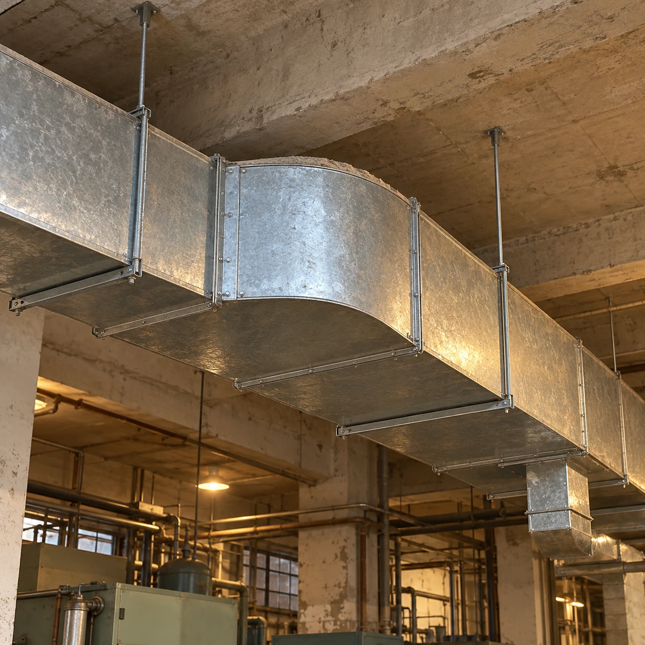
Turns in the main distribution run
trunk duct elbows
| Rectangular opening W × H (mm) | 500 × 300 / 800 × 400 / 1000 × 600 |
|---|---|
| Round nominal bore (mm) | 400 / 500 / 630 / 800 |
| Turn | 45° or 90°, horizontal or vertical |
| Construction | Radius or specified guided elbow |
| End arrangement | Matched openings; reducing construction separately defined |
| Interfaces | Flanges, supports and downstream takeoffs coordinated together |
Opening sizes do not establish trunk airflow capacity. Select the fitting for the actual flow, pressure and remaining distribution route.
Trunk duct elbows can be configured for the main route, branch layout and future service access.
A trunk elbow turns the main air route serving several branches. Its location can influence every outlet downstream, especially where a takeoff follows the corner closely. The fitting belongs in a coordinated distribution layout rather than an isolated parts list.
Look past the corner to the first branch
The velocity distribution leaving a bend may be uneven. A branch connected immediately into that region can receive air differently from a branch placed farther along a suitable straight section. Coordinate the bend, takeoff position and balancing provision instead of assuming branch flow follows opening area alone.
When a ceiling void forces the takeoff close to the turn, review that specific junction arrangement. A vane bank inside the elbow may change the outlet pattern, but it does not automatically make every downstream branch location equivalent.
Keep a size change visible in the design
A supply trunk often carries less air after branches leave it. If a change in section coincides with the turn, specify the inlet and outlet independently and define the transition. Do not allow an abrupt site-made reduction to appear simply because the next duct length has a smaller opening.
Return and extract trunks gather flow rather than distribute it, so the sequence must be considered in the actual airflow direction. A drawing viewed from the wrong end can conceal this distinction.
Support the route at the turn
The elbow and nearby branches can create a concentrated assembly load. Establish support positions before the run is hung, with allowance for insulation and maintenance. A branch connection should not become an accidental support for the main fitting.
Make expansion assessable
Retain the final layout and commissioned airflow information. Adding branches later changes the flow carried through upstream elbows and may increase their losses. An apparently spare connection does not prove that the fan and main route have spare capacity.
For equipment connections near the start of the trunk, see HVAC duct elbows. For handling a large main-run fitting, see large duct elbows.
Trunk duct elbows can be configured for the main route, branch layout and future service access.