Door Interlock Systems
Door Interlock Systems
| Door groups | Two-door airlock; selected controllers support three- or four-door groups |
|---|---|
| Controller footprint, W × H (mm) | 114.3 × 127 for two-door control; 177.8 × 127 for up to four doors |
| Logic supply | 12 or 24 VDC, matched to the selected controller |
| Field inputs | Door position, request-to-exit or access request, and configured alarm/override interfaces |
| Outputs | Dry relay contacts or compatible powered outputs; lock loads sized separately |
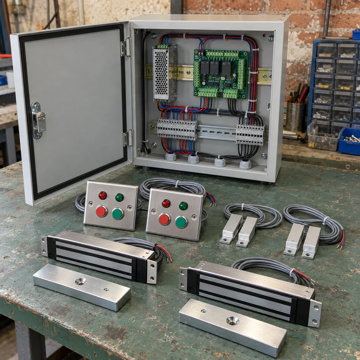
| Installation package | Controller, power supply, enclosure, contacts, status stations and selected locking interfaces |
Dimensions are controller footprints, not cabinet sizes. Enclosure depth, terminal access, heat clearance and cable space follow the approved assembly; the supply must cover the connected lock and peripheral loads.
Door grouping, indication, control enclosure and interfaces can be configured for the application and the approved access and emergency-release design.
Door interlock systems coordinate which door may open within an airlock or controlled passage. The controller combines requests, door-position signals and locking interfaces so that normal movement follows an agreed sequence rather than relying only on people remembering to close the opposite door.
Define the doors that belong to one sequence
A simple personnel airlock has two openings with a clear relationship: opening one prevents normal release of the other. A larger passage can have several doors, but they may not all need to inhibit one another. A door-group schedule identifies each permitted route and avoids creating a system that blocks an unrelated corridor.
Normally locked and normally unlocked arrangements behave differently. In a normally locked sequence, the controller grants a release after checking the other doors. In a normally unlocked arrangement, opening one door can cause the others to lock. The latter needs particular attention to simultaneous requests and opening attempts; it should not be treated as equivalent simply because both modes are called an interlock.
A normal release cycle
- Request entry. A push button, reader or other approved interface asks for passage through one identified door.
- Check the group. The controller evaluates the relevant door positions and the configured inhibit conditions before allowing normal release.
- Monitor passage. Position feedback indicates that the leaf has opened; a held-open condition can be reported instead of silently abandoning the sequence.
- Confirm return. Closure and any required lock feedback restore the group to its agreed state. A process delay is added only where the application calls for it.
The controller does not create room pressure or prove that airborne contamination has cleared. Where a recovery interval or environmental permissive is needed, its basis comes from the process and ventilation assessment. A convenient timer value is not evidence of room recovery.
Use feedback that describes the real condition
A lock output shows what the controller has commanded. A door contact shows the leaf's detected position. A separate lock-status signal can provide different information again. Treating these signals as identical can allow a poorly aligned latch or a partly open door to appear ready.
Contacts, cable routes and mounting brackets need to remain accessible for maintenance. The mechanism must also close consistently: a controller cannot compensate for a dragging leaf, failed closer or an obstruction at the threshold.
Size the electrical package as a system
The logic board's consumption is only part of the power requirement. Locks, indicators, readers and auxiliary equipment can dominate the load, especially during a release or recovery event. Select the supply, distribution and protection for the actual connected devices and cable lengths.
A dry contact is a switching interface, not a power source. Powered outputs must match the lock voltage and electrical load. Manufacturer relay limits and the behaviour of inductive loads belong in the selected assembly design rather than being inferred from the number of available channels.
Emergency release takes priority over normal sequencing
The normal airlock sequence must not obstruct the required escape route. The project design must establish the response to emergency release, fire-alarm signals, controller faults and loss of power, including any backup supply. These conditions should be agreed with the responsible fire and access specialists before the locking hardware is ordered.
An interlock controller is not, by itself, an approval for an emergency exit or a safety-rated machine-guard system. For the door assembly and escape hardware, review the relevant Emergency Exit Doors requirements alongside the control design.
Commission the exceptions as well as the normal route
Acceptance should include both permitted routes and cases such as simultaneous requests, a held-open door, an inconsistent contact, power interruption and return to service. Operators need a clear indication of whether entry is permitted, a door is busy or a fault needs attention.
Keep the door-group schedule, cause-and-effect description and component references with the handover record. For the physical door interface, see cleanroom doors. Communicating across the boundary can also reduce unnecessary opening requests through a suitably placed intercom station.
Door grouping, indication, control enclosure and interfaces can be configured for the application and the approved access and emergency-release design.