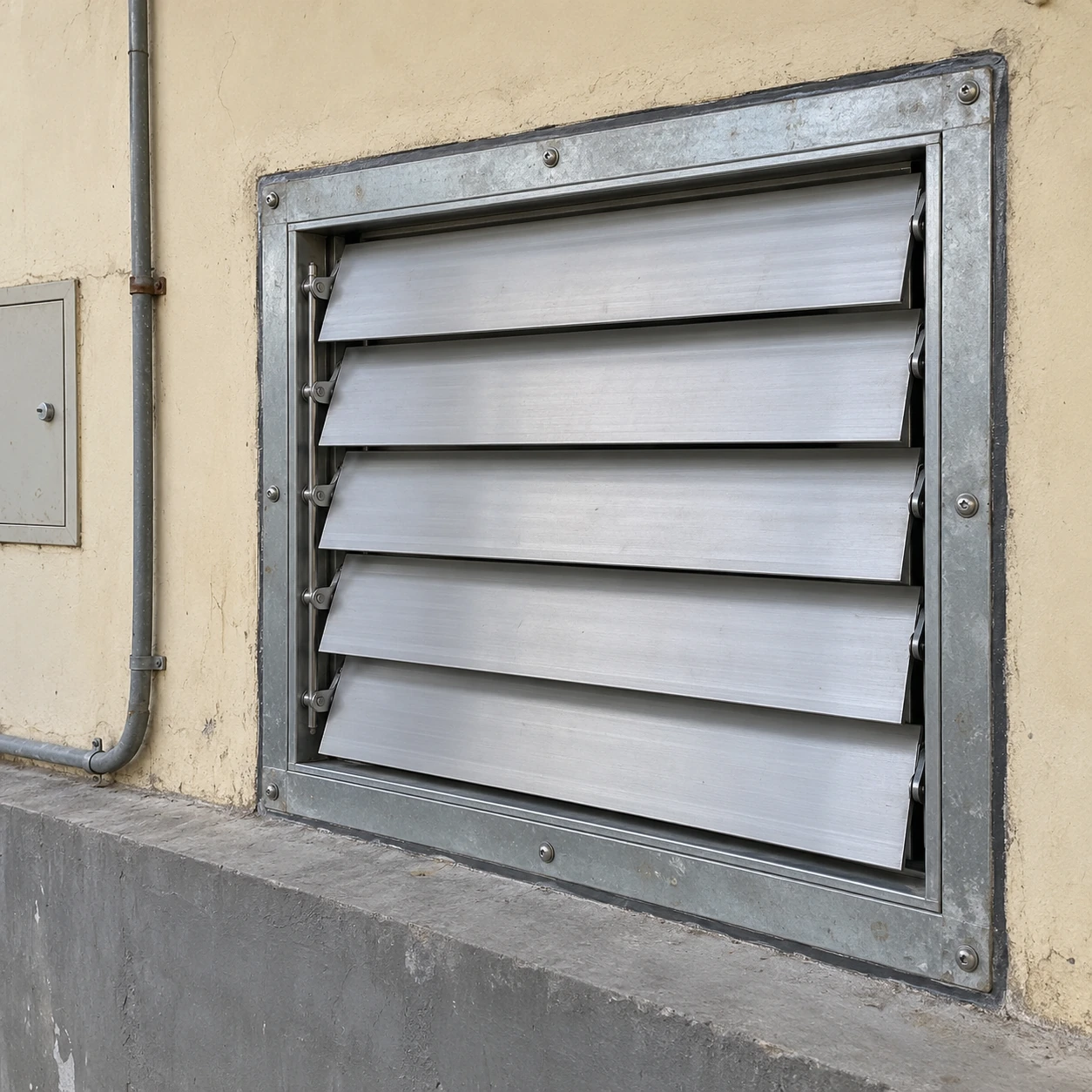
Air Volume Control Dampers
ventilation backdraft dampers
| Rectangular nominal W × H | 400 × 345 mm; 600 × 675 mm; 800 × 1005 mm |
|---|---|
| Air-path duty | Fresh-air intake, exhaust or an individual parallel-fan branch, selected for the system layout |
| Construction | Galvanized casing with aluminum blades; linked-blade or independent-blade mechanisms |
| Actuation | Pressure-operated non-return action; motorized opening and closure where the sequence requires it |
| Mounting | Horizontal duct or vertical duct with the corresponding approved blade orientation |
| Connection and access | Flanged or supported duct connection with access to pivots, seals and linkages |
| Selection conditions | Minimum and maximum airflow, reverse pressure, leakage requirement and terminal resistance |
W × H gives nominal connection dimensions, not the outside flange, casing depth or blade free area. The final assembly drawing coordinates the damper, duct and service opening. Performance belongs to the selected construction and duty.
Ventilation damper size, materials, connection and operating arrangement can be customized to the fan system, airflow modes and installation location.
Ventilation backdraft dampers help limit reverse airflow through an inactive fan or duct branch. Their position and operating mechanism need to match the ventilation arrangement, including low-speed operation, adjacent fans and the pressure conditions when the system stops.
Identify when the airflow changes direction
Reverse flow can arise when a fan stops, when another fan changes the pressure in a shared discharge, or when external conditions act on an intake or exhaust terminal. The damper needs to address the relevant air path. Fitting a shutter at the most accessible point does not always prevent the unwanted route.
| Ventilation arrangement | Question to resolve | Damper implication |
|---|---|---|
| A single fan connected to outdoors | What drives air through the opening when the fan is off? | Match closing direction and reverse-pressure capability to the terminal and fan arrangement. |
| Parallel fans sharing a discharge path | Can an operating fan push air backward through an idle branch? | Consider a non-return function at each affected fan branch, with adequate access and support. |
| A central extract fan serving several branches | Should unused branches remain open under the central fan's suction? | A passive one-way flap may open in the normal extract direction; scheduled isolation requires a separate control decision. |
| Variable-speed ventilation | Will the damper open and remain stable at the lowest required airflow? | Check low-flow behaviour as well as the maximum-duty pressure loss. |
These layouts are not interchangeable. Confirm where pressure is positive or negative in each operating mode and where air is intended to travel. The same damper orientation that works on one branch may be inappropriate on another.
A non-return flap is not an occupancy control
A passive damper responds to pressure direction, not to whether a room or production station is in use. If a shared extract fan keeps pulling air in the normal direction, a passive branch damper may stay open. Reducing airflow in an unused branch requires the appropriate control arrangement and consideration of the rest of the ventilation network.
Where a defined opening and closing command is needed, review motorized backdraft dampers with the fan sequence. Position feedback, airflow verification and any process interlocks are separate functions that should be specified deliberately.
Preserve the required ventilation at low speed
A damper selected only for peak airflow may perform differently when the fan slows down. The blades can remain partly open, increasing resistance relative to the available pressure, or move repeatedly near their opening threshold. Check the complete operating range against the chosen mechanism.
Adding another damper in series also adds another resistance. If a fan or terminal already contains a shutter, identify it during selection. Doubling the number of moving barriers does not automatically improve the usable ventilation arrangement.
Separate weather protection from reverse-flow control
An outdoor louver or hood manages the exposed opening, while a backdraft damper controls a moving air path. One component should not be assumed to provide all the functions of the other. Coordinate rain protection, screens and the damper so water and debris do not collect at the moving parts.
A dirty screen or obstructed terminal can reduce airflow and affect blade movement. Wind-related noise may require attention to the complete terminal arrangement rather than a heavier closing force applied to the damper alone.
Keep the service route accessible
Position the damper where its blades, pivots, seals and linkage can be inspected. A small access hatch is of limited use if the moving assembly cannot be reached or removed through it. Allow access after insulation, adjacent services and final panels are installed.
With the equipment safely isolated for service, inspect for deposits, frame distortion and contact between blades and nearby components. After maintenance, check the selected operating modes and the closing response. Persistent reverse flow can also pass through a different duct route, so a correctly closing damper should not end the investigation if the symptom remains.
Coordinate the fan, duct and control schedule
For a new installation, describe normal operation, reduced-speed operation, fan-off conditions and operation of adjacent fans. Provide the available fan pressure and the losses from terminals and other components. The Exhaust Fan Box and its duct accessories should be assessed as one air path.
For an existing system, record when the problem occurs and which fans are running at that time. This can distinguish a local blade fault from a pressure interaction elsewhere. General ventilation backdraft control does not establish fire separation, smoke-control performance or verified hazardous-air containment; those functions require their own specified equipment and system design.
Ventilation damper size, materials, connection and operating arrangement can be customized to the fan system, airflow modes and installation location.