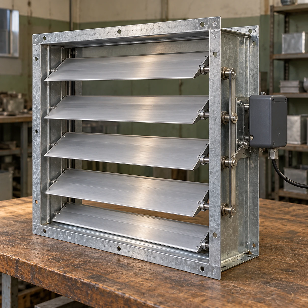
Air Volume Control Dampers
motorized backdraft dampers
| Nominal opening W × H | 305 × 305 mm; 457 × 457 mm; 610 × 610 mm |
|---|---|
| Construction | Galvanized steel frame, aluminum blades and external operating linkage |
| Operating sequence | Power-open with spring-return closure; other return arrangements require separate selection |
| Actuator supply | 24 V AC or 220–240 V AC, 50/60 Hz options; supply and actuator must match |
| Control and feedback | On/off command; open-position switch and fan interlock where specified |
| Mounting and connection | Horizontal or vertical mounting with a suitable mechanism; flange side coordinated with actuator access |
| Actuator sizing | Torque, number of drives, stroke time and service clearance determined for the complete damper |
Dimensions are nominal opening selections within a configurable rectangular range, rounded from inch-based sizes. They exclude the flange, actuator and moving linkage. Final frame dimensions, electrical details and service space are defined by the selected assembly.
Motorized damper dimensions, actuator supply, return action and feedback arrangements can be customized to the ventilation control sequence.
Motorized backdraft dampers use an actuator to open and close the blade bank instead of relying entirely on airflow to move it. They suit ventilation arrangements that need a defined opening command and a coordinated closing sequence when the associated fan stops.
Coordinate the damper with the fan
A motorized assembly can establish an open air path before a fan starts, which is useful when available airflow would not reliably lift a passive damper. The benefit comes from the control sequence as well as the actuator. Energizing a motor is a command; it is not evidence that the blades reached the required position.
- Request ventilation. The control system sends the opening command and permits the actuator to travel.
- Confirm the required position. Where specified, an appropriately adjusted position switch provides the permissive signal for fan operation.
- Run with an established air path. The fan and damper operate in their selected positions, with any required airflow monitoring handled by the ventilation controls.
- Stop and close in the agreed order. Coordinate fan run-down and damper closure so the fan is not operating against an unintentionally closed blade bank.
The correct response to a lost signal, failed position proof or power interruption should be defined before purchase. A spring-return design can move toward its selected return position when power is removed, but mechanical obstruction or damaged linkage can prevent complete travel. The return mechanism alone is not proof of an achieved seal.
Position feedback is not airflow measurement
An end switch indicates a mechanical position or travel point. It does not measure how much air passes through the duct. A fan may receive an open permissive while another obstruction in the system still limits ventilation. Use the required system monitoring for the process rather than asking one switch to prove both functions.
Identify the feedback type and how it will be used by the control panel. The wiring interface, voltage and contact arrangement must match the selected controls; installation and adjustment belong with qualified personnel following the supplied wiring information.
An open motorized damper allows a flow path
Once an actuator holds the blades open, the damper generally behaves as a control damper. It should not be assumed to close automatically against a sudden reverse flow while the open command remains present. If reverse flow during fan operation is part of the duty, specify how the system detects and responds to it.
Continuous modulation is a separate control requirement. For proportional flow adjustment, compare the appropriate Electric Volume Control Dampers arrangement instead of assuming a simple on/off motor pack provides regulation.
Leave working space around the actuator
The drive, crank arm and linkage can project beyond the frame. Space that is adequate for installing the damper may still be too small to remove a failed actuator or adjust a switch. Choose the flange side and access position before surrounding ductwork or insulation makes those parts difficult to reach.
Actuator torque must suit blade area, seals, friction and the pressure conditions during movement. A larger opening may require a different drive or multiple coordinated sections. Matching an actuator only by shaft diameter does not establish that it can move and hold the complete assembly under the intended conditions.
Use the symptom to narrow the inspection
| Observed behaviour | Items to inspect |
|---|---|
| Opening command is present but no travel occurs | Correct supply, control interface, actuator condition and mechanical obstruction. |
| Actuator moves but some blades remain closed | Linkage connection, coupling slip, section alignment and blade interference. |
| Fan does not start after damper travel | Position-switch adjustment and the complete permissive circuit; do not bypass the interlock. |
| Blades return but air still passes when closed | Seal condition, deposits, frame alignment and the specified leakage duty. |
Order the control arrangement with the hardware
The purchase description should include the normal operating state, desired power-loss position, fan permissive, feedback and physical access. Keep these details with the damper drawing so a later actuator replacement preserves the intended behaviour. Ordinary motorized backdraft equipment does not acquire a fire, smoke or emergency shutdown rating merely because it has spring return.
Motorized damper dimensions, actuator supply, return action and feedback arrangements can be customized to the ventilation control sequence.