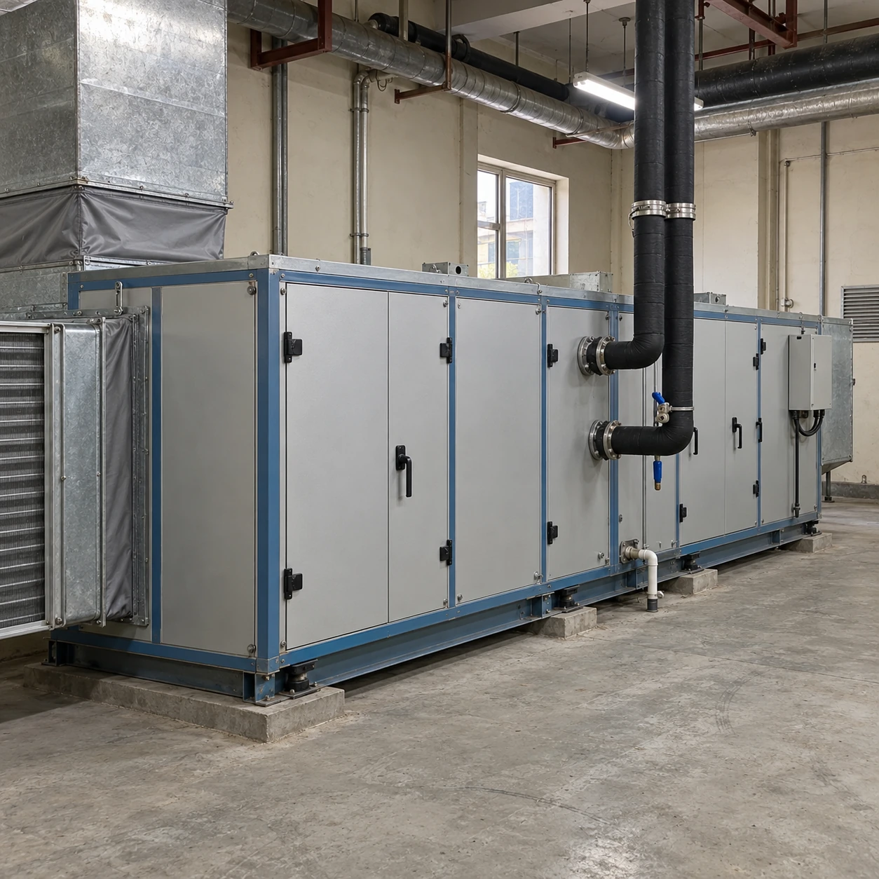
Air Handling Units
hvac air handling units
| Airflow duty options | 4000 / 6000 / 10000 m³/h at the selected operating pressure |
|---|---|
| Casing W × H (mm) | 1190 × 790; 1290 × 990; 1590 × 1090 |
| Coil circuit | Chilled-water/hot-water coils or a compatible DX arrangement |
| Air-side interfaces | Supply, return, outdoor and exhaust connections to suit the system layout |
| Fan and pressure control | Variable-speed fan; constant airflow or duct-pressure control as specified |
| Filtration monitoring | Selected filter stages with differential-pressure indication or alarm |
| Condensate provision | Drain pan and accessible drain connection; trap matched to section pressure |
| Control signals | Fan proof, temperatures, valve/damper commands, fault signals and agreed BMS points |
| Service arrangement | Coil handedness, access side, removable sections and plantroom connections coordinated together |
Casing heights exclude base rails, top dampers and projections. Full unit length, drain-trap clearance, pipe access and withdrawal space are defined by the final component arrangement.
HVAC air handling units can be customized to suit the air system, heating or cooling source, control sequence, connection layout and maintenance requirements.
An HVAC air handling unit sits between the air distribution system, the heating or cooling source and the controls that connect them. Selecting each part independently can leave the fan short of pressure, the coil operating at different water conditions from the plant, or the controller waiting for a signal that no other contractor supplies. A coordinated selection makes those interfaces explicit.
Connect the duties across the system
- Air distribution → fan selection
- Define the required airflow and the pressure allowance outside the unit. Include the connected ductwork, terminals and accessories in that allowance. The AHU selection must separately account for its own filter, coil and internal-section resistance so that losses are neither omitted nor counted twice.
- Heating or cooling plant → coil selection
- State entering and leaving fluid conditions, available flow, fluid composition and the air conditions through the coil. A change in chilled-water temperature or glycol content can change the result. Coil duty should be checked at the conditions the plant will actually deliver.
- Terminal devices → control sequence
- In a variable-air-volume system, terminal dampers change demand while the AHU fan responds to the pressure-control strategy. A constant-volume process has a different objective. Select the feedback signal and operating limits around the served system rather than around the fan alone.
Separate temperature control from moisture duty
A cooling coil removes moisture when its surface conditions cause water vapour to condense. The amount removed depends on the entering air and the coil's operating conditions. Reaching a supply-air dry-bulb temperature does not by itself demonstrate that the required moisture removal has occurred.
If heating is available from an air to water heat pump system, select the heating coil for that circuit's temperature range and available flow. Where the process requires added moisture, coordinate any HVAC steam humidifier with airflow, absorption space and the relevant humidity-control sequence.
Make drainage part of the arrangement
The fan's position determines whether the cooling section operates under positive or negative pressure. That pressure affects the condensate trap needed for water to leave the pan while maintaining the intended air seal. The unit base and drain route must leave room for the selected trap.
A drain connection shown on a drawing is not a complete drainage design. Keep the pan and trap accessible, coordinate the discharge route and protect the arrangement against the applicable operating conditions. The manufacturer's installation details should govern the final trap and connection configuration.
Write the operating sequence before choosing the point list
Start with the required operating states: stopped, starting, normal operation, reduced demand and fault response. Identify the commands and proof signals needed to move between them. A command to start a fan and confirmation that airflow is established perform different functions.
- Enable the required services. Coordinate the fan, dampers, heating/cooling availability and any process interlocks in the specified start sequence.
- Control the normal duty. Define which sensor governs fan speed, coil valves and supply-air temperature, with clear responsibilities between the AHU controller and the building system.
- Handle abnormal conditions. Establish the required response to fan failure, unavailable water flow, low-temperature protection or an external stop signal. These responses belong in the project sequence, not in assumptions about a generic controller.
- Expose useful operating information. Provide the agreed statuses, temperatures, filter-pressure alarms and faults. A communication connection is useful only when both systems understand the same points and command priorities.
Compare the installed result with the selected duty
Commissioning should establish that the connected system can achieve the intended airflow and air-treatment duty. Record the relevant air and fluid conditions, fan operating state, pressure readings and control response. A running motor or a completed network connection is not enough to establish that the whole system operates as selected.
Keep the final section drawing, wiring information, control sequence and component schedule together for maintenance. Changes made during installation should be reflected in those records, particularly revised filter arrangements, valve locations and sensor positions.
Send the air-system schedule, plant conditions and interface requirements through the quotation enquiry. For projects driven by occupancy patterns and building operation, compare commercial air handling units.
HVAC air handling units can be customized to suit the air system, heating or cooling source, control sequence, connection layout and maintenance requirements.