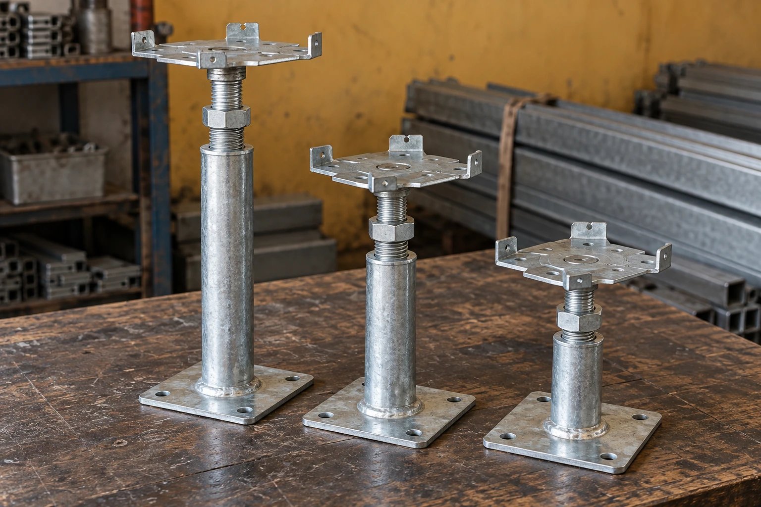
Raised Access Flooring
raised access flooring pedestals
| Material | Galvanized steel support assemblies |
|---|---|
| Pedestal height families | 20–2000 mm across distinct support constructions |
| Panel grid | 600 × 600 mm with the matching panel and head arrangement |
| Adjustment | Threaded height setting and specified locking arrangement |
| Head interface | Compatible panel seating, gaskets and stringer connections |
| Base fixing | Adhesive and/or mechanical connection to the project-specific detail |
| Special locations | Perimeter supports, bridging or independent frames where required |
The height range covers different pedestal families; one post does not adjust through the entire range. Pedestal height is separate from finished floor height and usable service clearance.
Pedestal family, head arrangement and fixing detail can be coordinated with the required floor level, panel construction and substrate.
Raised access flooring pedestals establish the floor level and transfer panel loads to the structural slab. Their performance depends on the head connection, post geometry, base fixing and supporting substrate working as one assembly.
Seat the panel correctly
The head must fit the panel corner or edge geometry. Gaskets may provide the specified contact and separation, while a compatible head can also locate stringers. A panel resting on an unintended edge of a head plate can appear level without being properly supported.
Adjust within its limits
Threaded adjustment compensates for the slab profile within the permitted range of the chosen support. Required thread engagement and locking arrangements come from that assembly's instructions. An excessively extended post or an improvised spacer changes the designed geometry.
Connect to sound material
The base needs an appropriate substrate and fixing method. Dusty surfaces, weak toppings, moisture or incompatible coatings can affect bonding. Mechanical fixings also need a suitable design and substrate; they are not an automatic cure for an unsuitable floor base.
Height changes the support problem
A taller floor provides more service space but also changes how lateral forces act on the understructure. Support selection should account for the complete floor height and the restraint arrangement, not simply the vertical weight each post appears to carry.
Stringers, bracing or other stabilization may be required by the selected system and project design. Keep those components in the load assessment. Removing a rail for cable access can alter the support arrangement even if the floor remains temporarily level.
Work around services without losing the load path
A pipe, trench or existing base may occupy the position where a pedestal would normally sit. Moving that support sideways changes the panel span and contact points. Resolve the obstruction with an approved bridging or independent support detail rather than shifting posts until the services fit.
The same principle applies at large openings and heavily cut perimeter panels. Special support locations should be drawn and included in the component schedule before installation.
Rocking is a symptom, not a diagnosis
A rocking panel may result from debris, a damaged gasket, incorrect head geometry, uneven adjustment or a loose base. Identify the cause before adding packing material. An improvised shim can conceal the problem and introduce a new unsupported contact.
Preserve the adjustment at handover
Complete fixing cure and level checks according to the selected system before opening the area to traffic. Record the pedestal family, connection details and any special support zones so later maintenance can identify what must remain in place.
For a replacement, provide the existing head, post and base details together with the required height. The panel construction must remain compatible; a pedestal that fits physically beneath the floor is not necessarily a correct system replacement.
Pedestal family, head arrangement and fixing detail can be coordinated with the required floor level, panel construction and substrate.