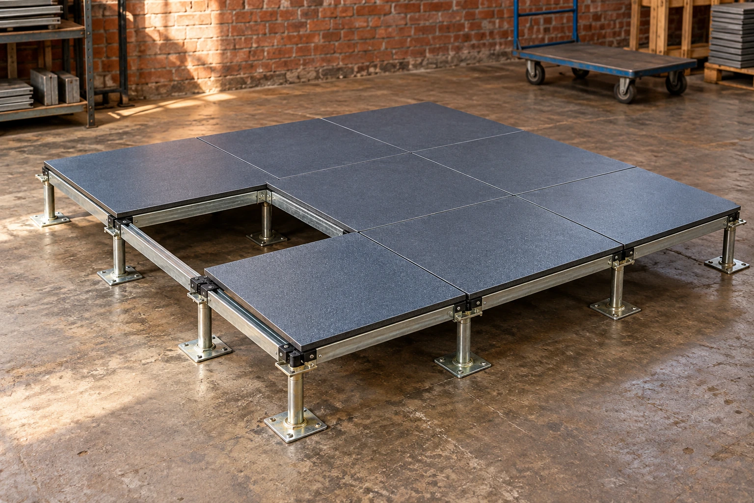
Raised Access Flooring
raised access flooring system
| Grid | 600 × 600 mm metric module |
|---|---|
| Panel choices | 31 mm steel-encapsulated wood core; 40 mm steel-faced wood core with bonded finish |
| Floor level | 40 mm faced assembly: 70–1320 mm finished floor height across matched support families |
| Support arrangement | Pedestal-supported or compatible stringered assembly |
| Panel retention | Lift-out or screw-fixed construction, selected as a complete system |
| Edge treatment | Supported cut panels, perimeter closures and transition profiles |
| Service accessories | Floor boxes, cable openings, outlet panels and suitable lifting tools |
A grid dimension does not establish interchangeability. Panel corner geometry, head plates, stringer position and finished thickness must belong to a compatible assembly.
The complete floor assembly can be configured around the room layout, equipment loads and required service access.
A raised access flooring system succeeds when every interface works together. The walking panels are the visible part; the supporting grid, boundary details and service openings determine how the floor behaves during installation, equipment movement and maintenance.
Follow the connection from surface to slab
Panels and finish
The finish affects cleaning, traction and access. Factory-bonded surfaces move with the panel, while loose finishes need a layout that allows panel removal. The edge detail must resist ordinary handling without obstructing the adjacent panel.
Heads and stringers
Panel corners need full seating. Where stringers are part of the design, they connect the supports and provide the intended edge relationship. Adding an arbitrary rail beneath a panel does not reproduce the tested assembly.
Pedestals and bases
Adjustable posts establish the level; their bases transfer forces into the slab. Adhesive, mechanical fixing or a specified combination must suit the substrate and project design. Dust, moisture and uncured materials can undermine that connection.
Resolve the exceptions before ordering
A rectangular field of full panels is straightforward. Columns, doorways, trenches and equipment penetrations are where coordination matters. A narrow cut panel still needs an appropriate support detail. A large opening may require a frame rather than simply removing part of the panel and its nearest pedestal.
Lay out the grid against these fixed features before the component schedule is frozen. This can reduce awkward slivers at the perimeter and keep routine access away from the busiest circulation route.
Three different heights
- Finished floor height
- The level of the walking surface above the supporting slab.
- Support height
- The particular pedestal assembly dimension, defined by its drawing.
- Clear service height
- The usable space below the lowest obstruction, including panels and stringers.
Using one of these dimensions in place of another can produce a floor that reaches the correct level but cannot accommodate the intended services.
Access and restraint must agree
Lift-out panels provide direct maintenance access. Screw-fixed panels add restraint but change the removal procedure and access time. In either case, services should not be attached in a way that prevents a panel from being removed safely. Partitions, heavy fixed equipment and large floor boxes may require separate structural support instead of relying on ordinary removable panels.
One coordinated schedule prevents missing parts
The bill of materials should tie panel types to their supports, edge details, fixings, gaskets and access tools. Identify special panels on the layout rather than treating every square metre as interchangeable. Keep the load assessment and installation method associated with that same schedule so a late finish substitution does not silently change the assembly.
For the understructure detail, review raised access flooring pedestals. A quotation can then distinguish the main floor field from perimeter work, service penetrations and separately supported equipment.
The complete floor assembly can be configured around the room layout, equipment loads and required service access.