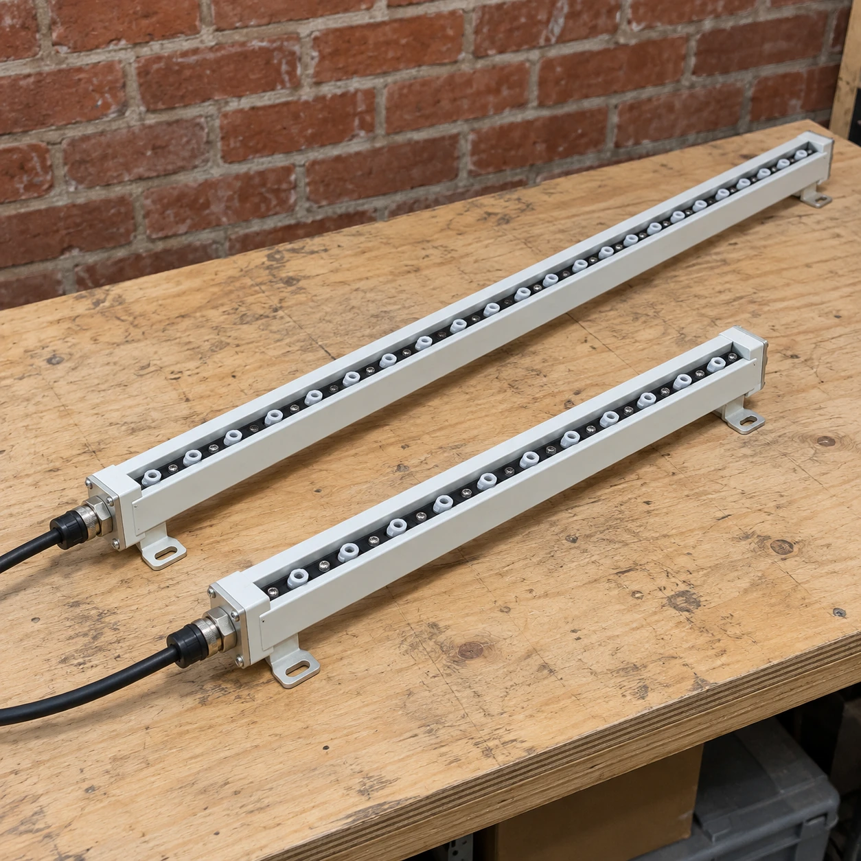
Ionizing Bars
ionizing bars
| Bar body length (mm) | 340 / 580 / 820 / 1120 / 1600 |
|---|---|
| Length definition | Bar length; allow additional space for connectors, brackets and cable bends |
| Input arrangement | 24 V DC integrated-electronics configuration with a matched supply |
| Ion delivery | Air-assisted or airless arrangement selected for the target distance |
| Emitter construction | Replaceable cartridge options with tungsten or silicon emitter elements |
| Mounting and monitoring | End supports; intermediate support where required; local indication or compatible remote signals |
Length, emitter arrangement, power supply and air connection are selected as a compatible assembly.
The bar length, mounting and control arrangement can be customized to suit the application.
Ionizing bars distribute positive and negative ions along a treatment line. Their value depends on where that line meets the material: a well-positioned bar can neutralize an exposed surface before the next operation, while a longer bar in the wrong position may leave the actual problem untouched.
Plan the treatment points before choosing the lengths
A converting line may generate charge at several contact-and-separation points. One bar near an unwinder cannot automatically control charge generated later at a nip, peeling station or discharge belt. Map the operations in sequence and identify where charged material first causes sticking, dust attraction or unstable transfer.
Several short bars can serve separate narrow lanes or changing product paths. A single longer bar can simplify an uninterrupted treatment width, provided its active region reaches both edges and its installation leaves sufficient support and service clearance. Physical body length and usable ionization coverage must be checked separately.
Choose a compatible equipment chain
Start with the bar, then specify its supply, connectors, control signals and mounting hardware together. A connector that fits mechanically does not establish electrical compatibility. Distinguish low-voltage input to integrated electronics from an external high-voltage supply feeding a different bar design.
Air assistance can carry ions toward a more distant surface, but it also introduces air preparation, pipe routing and running cost. Airless arrangements reduce those services where the available gap and process conditions allow effective treatment.
Give the ions a clear path
A grounded machine member between the emitter row and the product can intercept ions. Rollers, guards and extraction ducts therefore belong in the installation review. Keep the intended treatment area exposed without compromising machine guarding or allowing the bar to contact moving material.
For two-sided treatment, evaluate each exposed face and its charge history. Two bars placed opposite one another are not automatically an effective solution; their orientation and interaction need checking in the actual layout.
Make replacement and checking practical
Label the installed locations in the maintenance record and retain the exact supply and emitter details. Cleaning should be possible after safe isolation without dismantling the surrounding machine. Service access is especially important on bars fitted behind fixed guards or above a web path.
Commission the arrangement at the material position and at relevant line speeds. Recheck after changes to film, product width, gap or nearby metalwork. Use a defined measurement method and process acceptance limits, rather than relying on a power lamp alone.
For a web-specific selection, see anti static ionizing bars. Local operator tasks may instead suit Ionizing Air Blowers.
The bar length, mounting and control arrangement can be customized to suit the application.