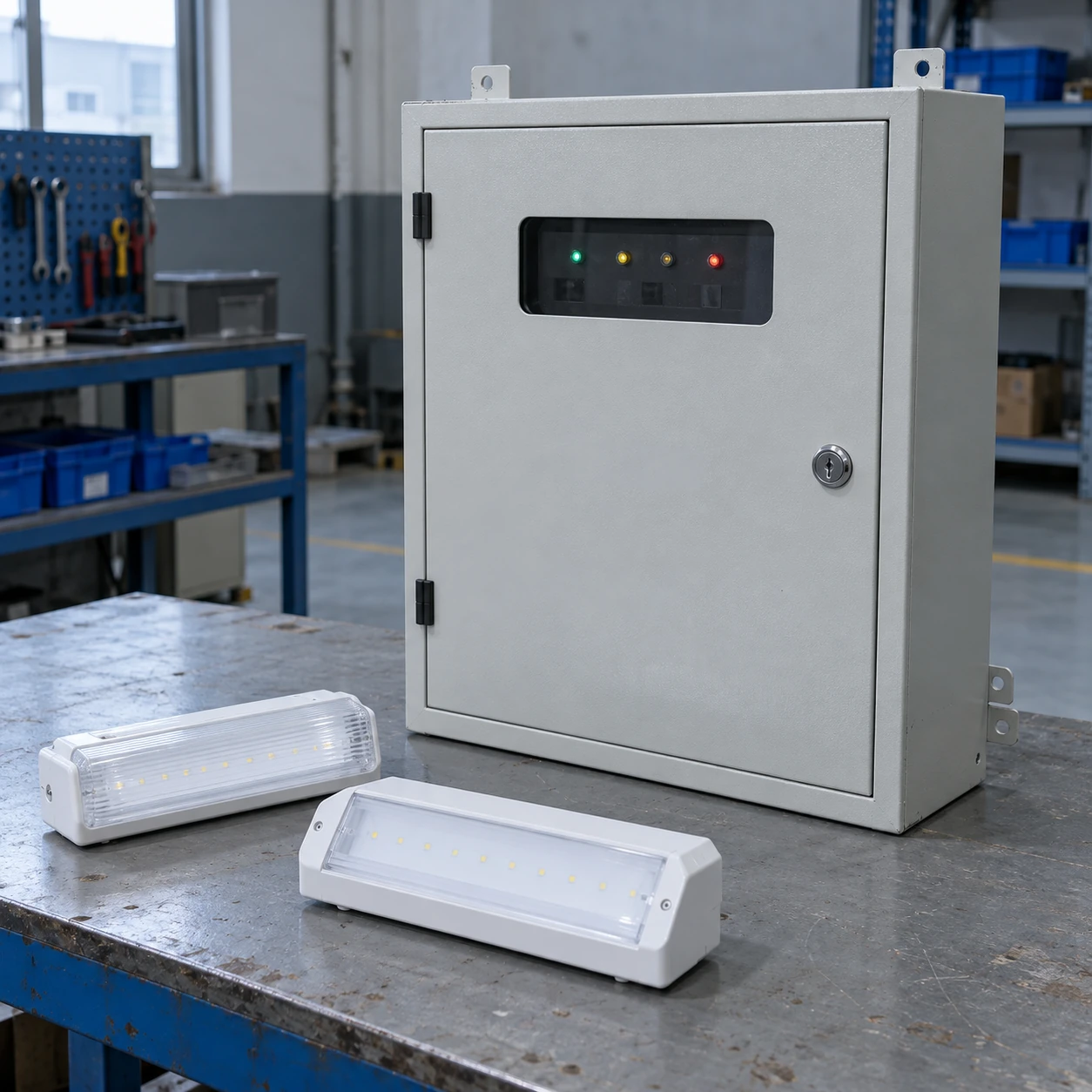
Emergency Lighting
dc emergency lighting system
| Nominal output | 24 V DC; the stated configuration family allows 19.2–28.8 V DC |
|---|---|
| Cabinet size choices (mm) | 340 × 330 × 90; 500 × 400 × 200; 587 × 460 × 187 |
| AC input option | 230 V AC ±10% |
| Outgoing circuits | 4-output or 8-output architecture; capacity and monitoring depend on assembly |
| Backup arrangements | Battery sets selected for the required duration and connected load; 1-hour and 3-hour configurations |
| Monitoring | Battery/charger and circuit status; individual luminaire monitoring requires compatible addressable equipment |
The dimensions describe three cabinet forms, not equal-capacity systems. A nominal 24 V marking is insufficient without the luminaire's full input range and cable-drop calculation.
The cabinet, circuit distribution, battery duty and compatible luminaires can be customized for the facility and applicable system requirements.
A DC emergency lighting system supplies compatible luminaires from a battery-backed DC distribution arrangement. A central system can move batteries into an accessible service location, but it also makes the cable routes, outgoing protection and luminaire voltage range part of the lighting design.
Follow the DC path from the battery to the lamp
A central DC arrangement combines a charger, batteries, supervision and outgoing lighting circuits. Compatible luminaires receive DC power through those circuits instead of carrying an individual battery at every fitting. This can put routine battery work in a more accessible location and provide a clear point for system status.
The central source is not the complete lighting system. The outgoing protective devices, cables, control signals and luminaires determine whether energy reaches the right places under the required failure conditions. A cabinet can show a healthy battery while a damaged branch or incompatible lamp leaves part of the route unlit.
Nominal voltage is not the whole operating range
A battery-backed DC circuit does not necessarily remain at its nominal voltage throughout charging and discharge. The luminaire must accept the full permitted supply range. It must also operate at the voltage available at its terminals after cable losses, particularly near the end of the specified discharge period.
For a given power demand, lower distribution voltage means higher current. Long runs and concentrated loads can therefore create significant voltage drop in a low-voltage system. Cable size and circuit grouping affect that drop; increasing the central battery capacity alone does not remove it. The electrical design should evaluate the most demanding load and route conditions using the selected equipment's limits.
Several shorter circuits
Dividing the route can reduce individual cable loads and contain the effect of a branch fault. It increases the number of protected outputs and wiring routes that need documentation.
Fewer extended circuits
Longer branches can simplify part of the distribution but place more lamps behind one output. Cable losses and the consequences of an open circuit or protective-device operation become more significant.
Distributed source cabinets
Several sources can shorten local circuits and limit the area affected by one cabinet fault. They add batteries and monitoring points, so the service arrangement becomes more distributed.
Use protection and monitoring intended for DC service
Protective and switching devices must be suitable for the actual DC circuit and fault conditions. An AC marking alone is not evidence for DC interruption. Cable protection, isolation, polarity and any required route integrity belong in the responsible electrical design and equipment instructions.
Monitoring can report the source, an outgoing circuit or individual luminaires. These are different levels of visibility. A circuit-level indication may not identify a single failed lamp, while addressable monitoring needs compatible luminaires and a supported communication arrangement. A common nominal voltage does not make products from unrelated monitoring systems communicate with each other.
Select the battery for its duty
Longer duration reduces the load that a given battery arrangement can support. Use the manufacturer's applicable load-duration data with the expected temperature and discharge limits. Battery chemistry and charging requirements must match the selected charger, and replacement batteries must follow the equipment instructions.
Leave an explicit capacity allowance where a future extension is expected. Otherwise, a seemingly small addition can consume reserve that the original design depended on.
Prove more than a healthy cabinet
Commissioning should address the required source and local-supply failure responses, operation of the designated lamps, fault indications and sustained emergency output. Arrange tests under controlled facility procedures and allow the battery to recover afterward.
Retain the circuit and luminaire schedule so that a later replacement or room alteration can be assessed against the actual system.
Choose DC distribution where its benefits are useful
A compact DC system can suit a defined group of compatible lights with manageable cable routes. An AC inverter may be more appropriate where existing mains luminaires are to be retained. The choice follows the load interface and distribution design, not a general assumption that low voltage is always easier. Compare the wider supply arrangements in emergency lighting, and coordinate the final equipment and installation with the responsible project designer.
The cabinet, circuit distribution, battery duty and compatible luminaires can be customized for the facility and applicable system requirements.