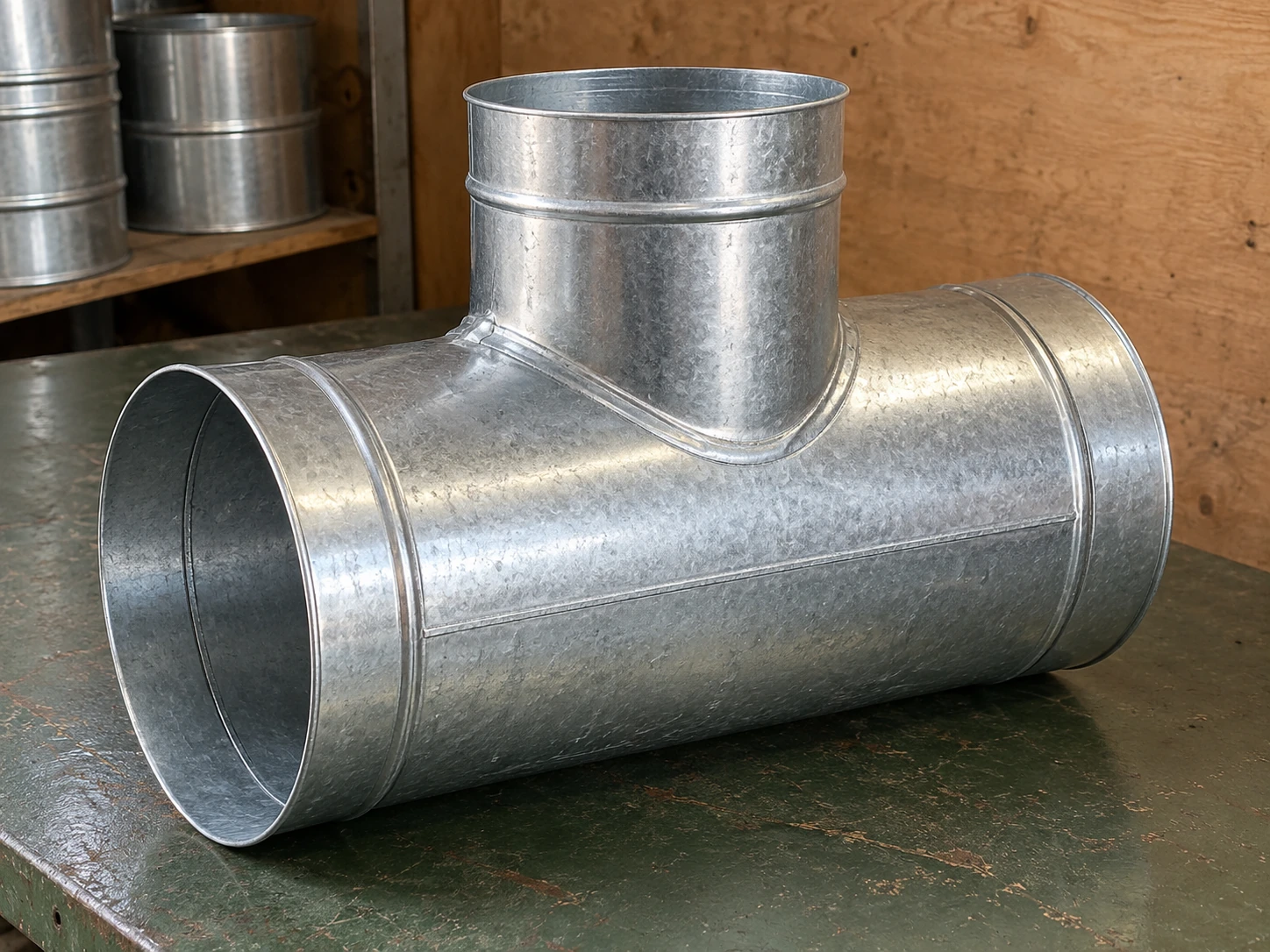
Duct Fittings
Duct Tees
| Junction layout | 90° side branch; equal or reducing round tee |
|---|---|
| Equal connections, D × d (mm) | 160 × 160; 200 × 200; 250 × 250 |
| Reducing connections, D × d (mm) | 200 × 160; 250 × 160; 315 × 200; 400 × 250 |
| Material options | Galvanized steel or stainless steel 304; match the air stream and cleaning conditions |
| End connections | Slip joints with compatible sealing and fastening; matched clamp collars; bolted flanges |
| Installation details | Body length, branch projection, joint engagement and support positions coordinated with adjoining ductwork |
D is the nominal diameter at both straight-run ends; d is the nominal branch diameter. The listed pairs are connection sizes, not overall dimensions. Exact end tolerances, wall thickness and fitting envelope depend on the selected construction.
Duct tees can be customized to suit the duct layout, connection sizes, material and operating conditions.
Duct tees connect a side branch to a continuing air duct. They serve supply, return and suitable extraction layouts in factories, workshops and commercial mechanical systems. Selecting the junction involves more than matching three openings: branch geometry, connection details and the resistance of the connected runs determine how it performs in the network.
Start with the route through the junction
A conventional tee has a straight path through the main barrel and a side branch meeting it at a right angle. In a supply system, some air continues along the main and some turns into the branch. In a return or extraction system, the branch flow can join air already travelling through the main. These two duties need different fitting-loss data, even when the metal component looks similar.
An equal tee keeps the same nominal diameter at all three ports. A reducing tee uses a smaller side connection while the two main ends remain equal. If the main also needs to change size, show that change separately on the layout; a smaller side branch alone does not provide a downstream reduction. A full tee replaces a length of duct, whereas a saddle take-off attaches to an opening in an existing run.
Choose the branch shape for the air stream
The compact side entry of a tee can fit a perpendicular route where a swept branch would need more space. A rounded branch throat can ease the turn, but its pressure loss still depends on the actual geometry and flow distribution. Allow room for the joint, insulation and tools as well as the fitting body.
For particulate extraction, an abrupt entry can increase local resistance and wear. Compare an angled branch with the tee during duct selection, especially where material is carried through the junction. A ventilation fitting should not be assumed suitable for abrasive, sticky or corrosive process exhaust solely because its diameter fits.
The tee does not set the airflow split
Two connected routes can receive different flows because their lengths, terminals and fittings impose different resistance. Matching outlet diameters does not make those routes share air equally. An oversized branch can also take more flow than the downstream main needs it to take.
Use the required flow in each route when selecting the junction and checking available fan pressure. If balancing is required, provide a suitable separate damper with reachable adjustment and measurement positions. Keep measuring points away from highly disturbed flow where the selected measurement method requires a straight approach.
Match the joint before ordering the fitting
- Slip connection
Check which part fits inside the other, the insertion depth and the seal position. A nominal diameter does not specify every mating tolerance. Rounded, undamaged ends help assembly; a distorted collar can create a leakage path even when fasteners hold the pieces together.
- Clamp connection
The collar profile, clamp and gasket must belong to a compatible connection arrangement. A clamp sized by diameter alone may not seat over a different rolled edge. This option is useful when sections must be removed for cleaning or a production layout changes.
- Flanged connection
Match the flange profile, bolt pattern, gasket and access for tightening. Include the flange projection when checking a crowded service zone. The nominal airway may fit while the external joint clashes with a beam or neighbouring pipe.
Keep the fitting supported and accessible
A branch should not hang from the tee collar as an unsupported load. Coordinate hangers for the connected runs so their weight and misalignment do not distort the junction. Leave access to removable connections and any nearby damper; burying them behind permanent finishes makes later cleaning and adjustment harder.
Choose the metal and seal together for the air temperature, moisture and contaminants. Stainless construction does not make every gasket chemically compatible. Where cold air can cool the fitting below the surrounding dew point, continue the specified insulation and vapour-control treatment around the branch. Inspect and test the installed joints before they become concealed.
A useful branch sketch prevents mismatched deliveries
Mark the airflow arrows, both main connections, the side connection and the required branch orientation. Add the connection system, available installation space and whether the air is clean, humid or carrying process material. For rectangular interfaces, identify width and height at each port rather than treating them as an equivalent round diameter.
Coordinate the tee with the adjoining ventilation ductwork. Where a final flexible connection is needed, select it from the flexible air duct range with its own support and routing requirements. These interface details allow the fitting and its accessories to be quoted as a compatible assembly.
Duct tees can be customized to suit the duct layout, connection sizes, material and operating conditions.