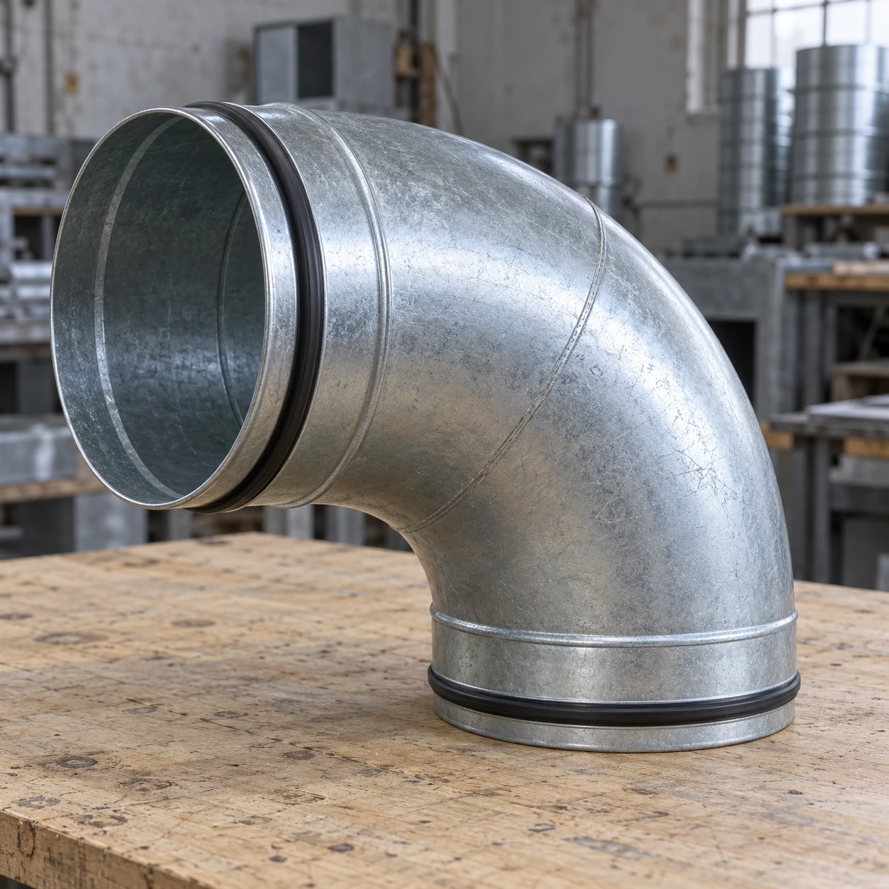
Circular connections and radius selection
round duct elbows
| Nominal bore D (mm) | 100 / 125 / 160 / 200 / 250 / 315 / 400 |
|---|---|
| Angles | 15° / 30° / 45° / 60° / 90°, by construction |
| Body form | Pressed bend or segmented fabricated bend |
| Centerline radius | R ≈ 1D or 1.5D constructions; other geometry by specification |
| Connection | Plain spigot, gasketed spigot, clamp or flange |
| Material | Galvanized steel or selected stainless steel |
R is measured to the duct centerline and D is nominal bore. Radius and end engagement are separate dimensions.
Round duct elbows can be configured for the diameter series, connection system and available bend space.
Round elbows connect circular ducts without changing cross-section. The nominal diameter identifies the size family, while the radius and straight end lengths determine how the bend fits the route. Both must be defined before replacing an existing fitting.
Pressed and segmented forms
A pressed bend uses shaped shell pieces to form the curve. A segmented bend builds the direction change from connected sections. The available sizes, seam arrangement and fabrication method differ, so compare the actual fitting drawing rather than treating one appearance as a universal quality grade.
For larger diameters or special angles, fabrication can provide a route that a small standard pressed component cannot. More segments also mean more joints to manufacture and seal.
Read the radius convention
A centerline radius is measured through the middle of the passage. An inside radius starts at the throat. These values cannot be substituted for each other on a drawing. Confirm the convention, then include the end tangents and connection engagement when checking the installed footprint.
A longer radius occupies more space. Its value should be assessed with the actual airflow and surrounding fittings; it should not be sold as a fixed percentage energy saving.
A matching nominal bore is only the first fit check
A male spigot normally engages a compatible female duct end; two similar-looking male ends may require a coupling. Gasket profiles, insertion depth and retaining methods must match the chosen system. Mixed suppliers can use the same nominal diameter while differing in the details that make the joint seal reliably.
Inspect roundness after handling. An ovalized end can displace a seal or leave uneven engagement. Correct transport protection is particularly useful for thin collars and large loose fittings.
Rotation establishes the route
Before locking a circular connection, set the plane of the elbow relative to the next section. Two turns in different planes create a spatial offset that is not fully described by one plan view. Record the final orientation where a future replacement must reproduce it.
For a defined right-angle turn, see 90 degrees duct elbows.
Round duct elbows can be configured for the diameter series, connection system and available bend space.