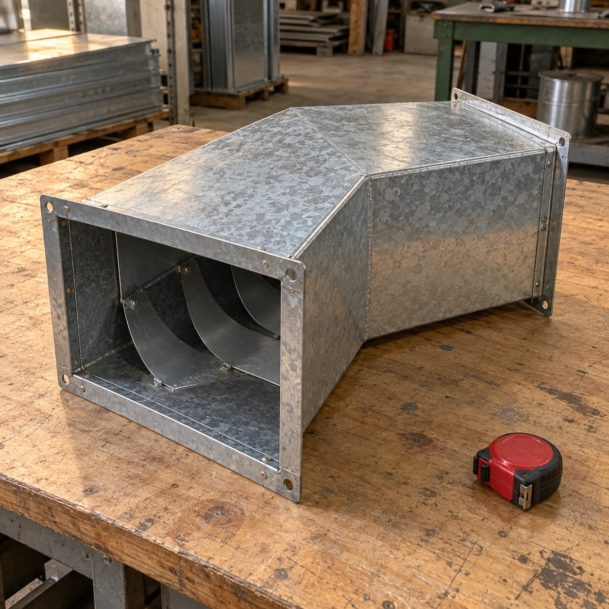
Opening orientation and replacement fit
duct elbows rectangular
| Opening W × H (mm) | 300 × 200 / 500 × 300 / 800 × 400 |
|---|---|
| Inlet / outlet | Equal opening or separately defined transition ends |
| Direction | Horizontal or vertical turn, identified on drawing |
| Angle | 45° or 90° |
| End frames | Slip connection or matching rectangular flanges |
| Internal arrangement | Clear radius passage or specified vane assembly |
State both end orientations. Opening dimensions do not define the overall heel, straight-leg length or bolt pattern.
Rectangular elbow dimensions and interfaces can be configured for the installation and service route.
When ordering rectangular elbows, a width and height alone do not describe the fitting. The turn may be across the wide face or the narrow face, and the two ends may appear reversed when viewed from opposite sides. A simple coordinated drawing prevents a correctly sized opening from arriving in the wrong orientation.
Record the interface in three views
- Look into the inlet. Identify width, height, airflow direction and the side on which the turn begins. Use the same viewing convention on the purchase drawing and installation drawing.
- Show the turn in plan or elevation. Mark the throat, heel and straight ends. Include obstructions such as a beam, cable tray or access door that determine the usable envelope.
- Look back from the outlet. Record the mating flange, hole positions and any change of opening. A centered connection and an offset connection require different fabrication even when the end sizes match.
Replacement work exposes hidden differences
An existing elbow may have an older flange profile or a nonstandard straight end added during installation. Measure the actual connection rather than relying on a nominal size marked on an old drawing. Check the distance between fixed duct ends after allowing for gasket compression and the intended joint assembly.
Do not pull the adjacent duct into position with the flange bolts. Forced alignment can distort the frame, open corners and load the supports. A short adjustment piece or a revised elbow leg is often more maintainable than a strained joint.
Room for the last fixing
The back corner of a flange is easy to overlook above a ceiling. Leave tool access on all sides and decide the assembly sequence before the fitting is lifted into place. External insulation increases the space needed around the completed joint.
Room for future removal
Consider which neighboring section can be disconnected. A fitting trapped between rigid ends may need an accessible removable spool. Locate that joint where its gasket and fasteners can be serviced.
For the airflow consequences of the shape, compare rectangular duct elbows.
Rectangular elbow dimensions and interfaces can be configured for the installation and service route.