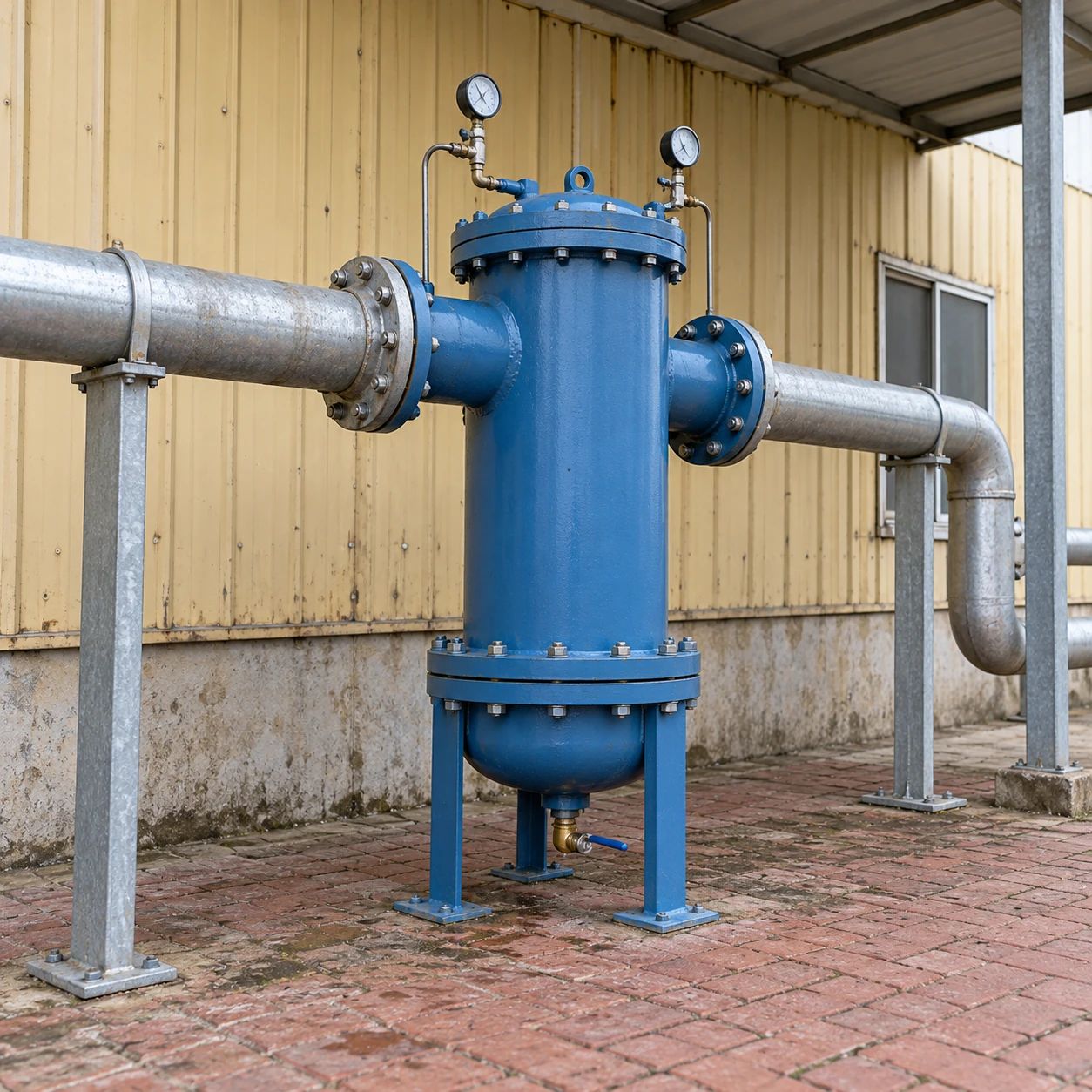
Compressed Air Filters
high flow compressed air filter
| Connection options | DN50, DN65, DN80, DN100 and DN150 nominal flanged ports |
|---|---|
| Vessel shell diameters | 114.3, 139.7 and 219.1 mm outside barrel diameter for selected vessel sizes; not flange outside diameter |
| Construction | Coated steel pressure housing; specified stainless designs for particular duties |
| Element arrangement | Single larger element or multiple elements within the selected vessel |
| Filtration duties | Particulate retention or coalescing aerosol removal; carbon adsorption selected as a separate stage |
| Pressure selection | Standard flanged designs up to 16 bar(g), subject to the assembly's stated temperature limits |
| Drain arrangement | Sized condensate drain with accessible collection connection |
| Sizing information | Normal and peak reference-volume flow, minimum line pressure, inlet temperature and permitted pressure loss |
DN is a nominal connection designation. Shell diameter, flange dimensions, installed height and element withdrawal space are different dimensions and are defined on the selected assembly drawing.
Housing size, flanges, element arrangement, drainage and service provisions can be customized for your air demand and installation layout.
A high flow compressed air filter treats a larger air demand while keeping pressure loss and service access manageable. Larger ports help, but capacity depends on the complete flow path, the element area, operating pressure and the filtration duty.
A large port can hide a restricted air path
The inlet connection, internal passages, element and outlet all contribute to pressure loss. A housing with generous flanges can still be undersized if its element area is insufficient for the selected grade. Equally, an adequate vessel can be restricted by small isolation valves or abrupt pipework reductions.
Check capacity at the lowest pressure expected during peak demand. Published flow tables usually state a reference volume and operating conditions; these must be retained when comparing equipment. Actual compressed volume and free-air volume are different quantities. The filter should be evaluated with the selected element in its relevant operating condition, including wet pressure drop for a coalescer.
Choose the service arrangement as well as the size
| Arrangement | Useful characteristic | Installation consideration |
|---|---|---|
| Single vessel | One pressure housing and one main service location. | Production may need to stop for service; allow handling space for the closure and elements. |
| Multiple-element vessel | More filtration area within a common pressure boundary. | Element identity, sealing and replacement access must suit the complete set. |
| Parallel trains | Can distribute demand or provide a separately sized standby route. | Verify flow sharing and remaining capacity when one train is isolated. |
Two smaller units do not automatically provide full standby duty. If both are needed for the normal peak, either one alone may be overloaded during maintenance. The systems layout should define the intended operating mode.
Plan the vessel's physical handling
Reserve the specified space for opening the service closure and withdrawing the longest element. Confirm how components will be supported or lifted, and keep the access route clear of adjacent pipes and cable trays. A compact footprint can still require substantial temporary service space.
Flange alignment and independent pipe supports protect the vessel from external loads. The bolting pattern, pressure class and gasket arrangement must match the approved installation; a common DN size alone does not establish compatibility.
Keep condensate removal proportional to the duty
Higher air demand can bring a greater liquid load, particularly during startup or changes in upstream cooling. Select the drain for the actual condensate duty and pressure range, and route its discharge into the site's suitable collection or treatment system.
A failed drain can cause liquid carry-over despite ample element area. Make drain service accessible and monitor its operation alongside differential pressure and the element replacement schedule.
Buy for the present load and the planned addition
Provide the current demand profile and identify which future users are committed rather than assuming every machine operates at full demand simultaneously. The supplier can then check a justified expansion allowance against pressure loss, operating range and service cost.
High flow describes capacity, not a high pressure rating. Booster duties require a separately specified high pressure compressed air filter. shengtongJH coordinates the vessel, element and installation interfaces around the actual duty.
Housing size, flanges, element arrangement, drainage and service provisions can be customized for your air demand and installation layout.