Compressed Air Filters
compressed air filter systems
| Network arrangements | Central treatment; local point-of-use filtration; combined central and branch treatment |
|---|---|
| Continuity options | Single train with planned shutdown; separately isolated parallel treatment trains |
| Small branch connections | 1/4, 1/2, 3/4 and 1 in nominal threaded ports |
| Larger branch connections | 1½ and 2 in threaded; DN50, DN80, DN100 and DN150 flanged options |
| Treatment selection | Particulate, coalescing and carbon stages selected independently for each duty |
| Water management | Compatible dryer interfaces and drainage at the relevant stages |
| Monitoring locations | Central outlet and critical downstream use points, as required by the process |
| Expansion review | Peak simultaneous demand, minimum line pressure, additional pressure loss and standby capacity |
Connection sizes describe line interfaces, not complete system footprints. Each train has its own arrangement drawing, operating limits and access requirements.
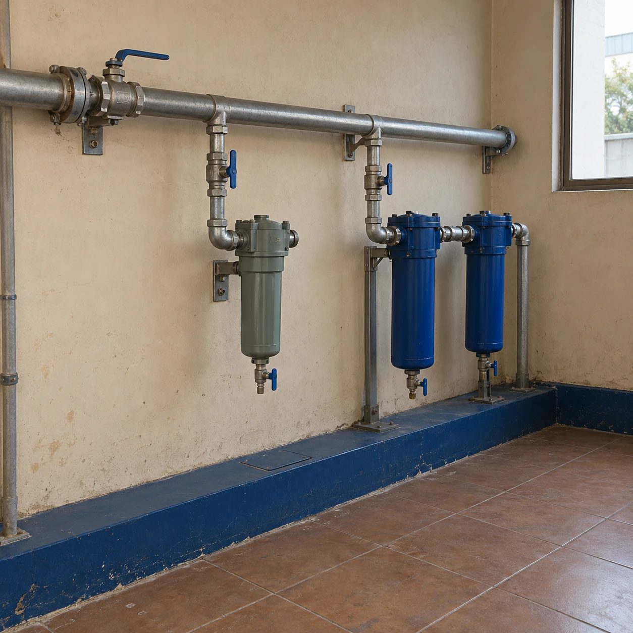
Central, branch and parallel filter systems can be customized for the different air demands, maintenance arrangements and expansion plans of your facility.
Compressed air filter systems can serve a whole distribution network, individual production areas or a small group of critical machines. The right arrangement follows where contamination is introduced, which users need additional treatment and how production will continue during maintenance.
Match the layout to the users
Central filtration
A common treatment train simplifies access and routine servicing. It suits users with compatible requirements, but long downstream pipework can introduce new particles or allow moisture to condense if the drying duty is insufficient.
Local filtration
Filters close to individual equipment can deal with contamination from the final branch and provide extra treatment where it is needed. More locations mean more drains, elements and service points to manage.
Combined treatment
A central baseline with selected local stages often fits mixed industrial demands. The local unit has a defined additional job, rather than repeating every central stage at every machine.
Separate quality requirements before separating pipework
An ordinary actuator line and an oil-sensitive process do not necessarily need the same treatment. Record the required particles, water and oil limits for each use, along with the location at which they must be met. This makes it possible to decide whether to treat the whole supply to a common level or add a dedicated branch.
Local adsorption or precision filtration should receive air within its inlet limits. A small final filter cannot compensate for uncontrolled liquid carry-over from the main system. Where specialist product-contact or instrument requirements apply, include the applicable measurement and acceptance procedure rather than relying on a general label such as clean air.
Parallel capacity and standby capacity differ
Two trains sharing normal demand may both be needed to meet the total peak. Taking one out of service can then overload the remaining equipment. If maintenance continuity is required, verify the duty that each available path can carry under the intended operating arrangement.
Valve positions and flow distribution matter. A parallel line with lower resistance may receive more than its share of flow, while a common drain or downstream connection can remain a single point of interruption. Document the service route and the checks needed before returning a train to operation.
A bypass preserves flow only under agreed conditions
Bypassing treatment may be acceptable for a limited noncritical task, but it can deliver untreated air to every connected user. The decision belongs to the process requirements and operating procedure, with clear identification of the affected equipment.
Where untreated air is unacceptable, use an appropriately designed alternative treatment path or schedule a shutdown. A simple bypass line should not be presented as full redundancy.
Expand against demand and pressure, not floor area
Adding several machines can change peak demand even when daily average consumption rises only slightly. Revisit the filter and dryer capacities, the smallest fittings and the pressure available at the furthest user. Retain the same flow reference basis when comparing new and existing equipment.
Build a service register around the physical locations: housing and element identity, drain type, isolation point, replacement interval and monitoring results. This helps prevent the correct element being installed in the wrong branch, and lets maintenance teams distinguish a loaded filter from a network pressure problem.
shengtongJH can coordinate the equipment scope for a staged upgrade. Begin with a marked air-network layout and the required duty at each user; the detailed components of an individual train are covered on the compressed air filter system page.
Central, branch and parallel filter systems can be customized for the different air demands, maintenance arrangements and expansion plans of your facility.