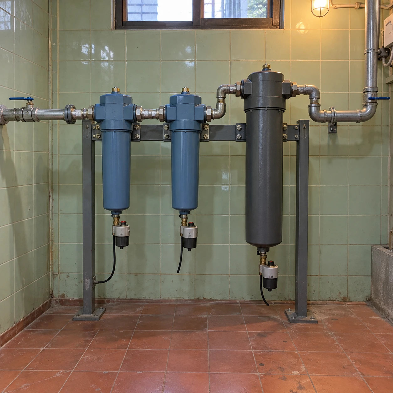
Compressed Air Filters
compressed air filter system
| Assembly formats | Individual wall-mounted stages; connected service panel; floor-mounted treatment rack |
|---|---|
| Threaded line sizes | 1/2, 3/4, 1, 1½ and 2 in nominal connections |
| Flanged line sizes | DN50, DN65, DN80 and DN100, selected for the process flow |
| Treatment stages | Bulk-liquid separation, particulate filtration, coalescing and optional carbon adsorption |
| Dryer interface | Refrigerated or adsorption dryer selected separately for the required water-vapour duty |
| Drain provision | Dedicated liquid discharge at the applicable separator and coalescing stages |
| Service arrangement | Isolation, controlled depressurisation, accessible elements and defined bypass policy |
| Acceptance points | Outlet pressure, relevant air-purity measurements and drain operation at agreed operating conditions |
Nominal ports do not define total rack dimensions. Equipment spacing, bowl withdrawal and valve access are fixed on the system arrangement drawing after the stages are selected.
The filter sequence, rack, connections, drains and dryer interfaces can be customized around your process and available installation space.
A compressed air filter system is a coordinated treatment path. Its stages protect each other and address different contaminants, while the pipework, drains and measurement points determine whether the intended air quality reaches the process.
Build the sequence around the incoming air
Start at the point where the treatment train receives air. Temperature, pressure, liquid carry-over and contamination determine the load on each stage. A fine coalescer should not be expected to handle uncontrolled slugs of water. Appropriate upstream cooling, separation and drainage reduce that burden before the air enters precision filtration.
Next define what the process actually requires. A particulate-sensitive valve bank, an oil-sensitive coating line and an instrument supply may need different combinations. More housings do not automatically produce better air; each stage needs a clear purpose and a compatible operating range.
Give every stage a specific job
- Remove bulk liquid where it forms. A separator and working drain address the liquid load following cooling. They are distinct from a fine aerosol filter.
- Protect the downstream treatment. Select particulate and coalescing stages to control the solids and oil aerosols that would foul later equipment. The required grade and sequence depend on the selected dryer and adsorber.
- Manage water vapour. Specify a dryer where the required dew point cannot be achieved by liquid removal. Confirm its inlet conditions and include any protective prefilter or dust afterfilter required by its design.
- Address remaining oil vapour when needed. A suitable carbon stage works on conditioned air. Include downstream retention of carbon fines where the chosen unit requires it.
- Protect the route to the process. Keep downstream pipework clean and consider local final filtration if the distribution line can reintroduce contamination.
This sequence identifies the jobs to be done; the final physical order and equipment selection follow the chosen manufacturers' installation requirements.
Budget pressure loss across the whole train
Each housing, valve, dryer and pipe fitting consumes part of the available pressure. Review the combined loss at the expected peak demand, including the element's service condition. A generous filter connection cannot compensate for a restrictive bypass valve or undersized manifold.
Keep the flow basis consistent through the equipment schedule. A dryer capacity quoted at one inlet temperature and a filter capacity quoted at another pressure are not automatically compatible. Selection should use the actual worst relevant conditions for each component.
Design for a controlled shutdown
Provide access for the largest element or bowl to be removed without dismantling neighbouring equipment. Isolate and depressurise the service section according to the equipment instructions, accounting for trapped pressure between valves.
An untreated bypass can preserve airflow while losing the required purity. If that is unacceptable, a parallel treatment path must be capable of supplying the required duty during maintenance. The operating procedure should state which route may be used.
Accept the result at a defined outlet
Commissioning should cover more than a leak-free pipe connection. Confirm the stages and element identities, the drains, operating pressure and the agreed air-quality measurements at a stated location and load. Retain the baseline for later troubleshooting. A filter test report is evidence about a component under its test conditions, not a certificate for the whole installed network.
For one treatment train, shengtongJH coordinates the equipment interfaces and supply scope. Where several areas require different grades or uninterrupted service, compare the broader arrangements on compressed air filter systems.
The filter sequence, rack, connections, drains and dryer interfaces can be customized around your process and available installation space.