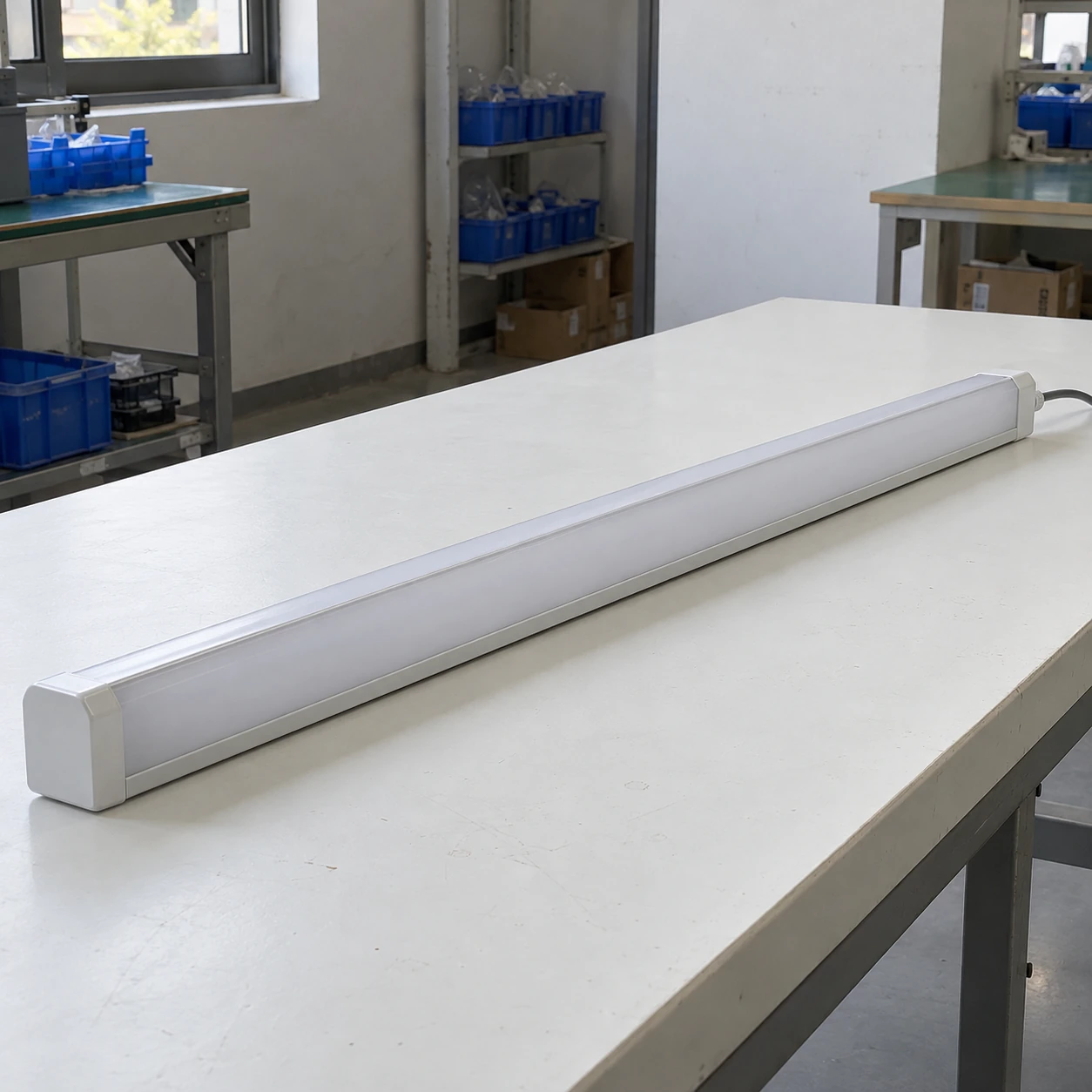
Cleanroom Lighting
led cleanroom lighting
| Narrow grid formats | 600 × 150; 900 × 150; 1200 × 150 mm (L × W) |
|---|---|
| Construction | Coated sheet-metal housing with a smooth safety-glass optical face |
| Light colour | 4000 K white; alternative colour or spectrum selected for the process |
| Supply | 220–240 V AC with a matched LED driver |
| Control interface | Fixed output or DALI dimming with compatible control equipment |
| Installation details | Grid integration, service side, cable entry and driver position matched to the ceiling |
The listed L × W values describe narrow grid-fitting formats. Housing depth, mounting hardware and maintenance clearance depend on the selected assembly.
LED format, optical face, driver and dimming arrangement can be customized for the application and installation conditions.
LED cleanroom lighting combines the light source, driver, optical face and enclosure into a working assembly. Good selection considers the light delivered to the task, how the driver behaves and how the unit can be maintained after installation.
Compare complete luminaires, not LED chips
The output of an LED component is not the light output of a finished fixture. The diffuser, internal optics, drive current and operating temperature all affect what leaves the luminaire. For an energy comparison, use the complete assembly's input power and delivered light output under comparable conditions.
A lower-wattage replacement can be useful when it maintains the required light on the task. It can also be an unsuitable replacement if its distribution leaves dark areas between fittings. Retaining the old fixture count is not a substitute for checking the new layout.
Driver behaviour
Light output follows the electrical drive. A driver and dimmer that work poorly together may cause unstable low-end dimming or temporal light modulation. Evaluate the intended operating range, including reduced-output settings, instead of assuming that every LED is flicker-free.
Optical quality
Colour temperature describes the appearance of the light; colour rendering addresses how objects appear under it. Neither property alone establishes good inspection conditions. Surface finish, viewing angle and the visibility of specific colours also matter.
Heat path
LEDs and drivers still produce heat. A sealed body needs a suitable thermal path and an installation environment within its limits. Covering the housing with insulation or trapping a driver in an unplanned enclosure can change its operating conditions.
Keep the dimming interface consistent
A dimmable driver must match the controller and wiring arrangement. The control interface belongs in the order schedule, along with the required range and the expected behaviour after a power interruption. A fixture fitted for simple switching cannot be assumed to provide addressable dimming later without changing components.
For camera-based inspection, check the light with the intended exposure settings and production motion. A source that looks steady to an operator can still interact with image acquisition. The relevant acceptance check is the actual inspection result, not a camera photograph used as a universal flicker test.
Choose a maintainable replacement path
An accessible driver can allow a targeted repair, provided its electrical output and control settings match the LED module. A physically similar replacement driver can still be unsuitable. Record the selected component specifications and whether replacement is permitted from the room side or from above.
Replacing a fluorescent lamp with an LED tube also changes the electrical and thermal arrangement. Assess the complete fitting, wiring and enclosure condition before treating it as a straightforward lamp swap. Where the housing or sealing is already compromised, a complete lighting unit can give a clearer replacement scope.
LED format, optical face, driver and dimming arrangement can be customized for the application and installation conditions.