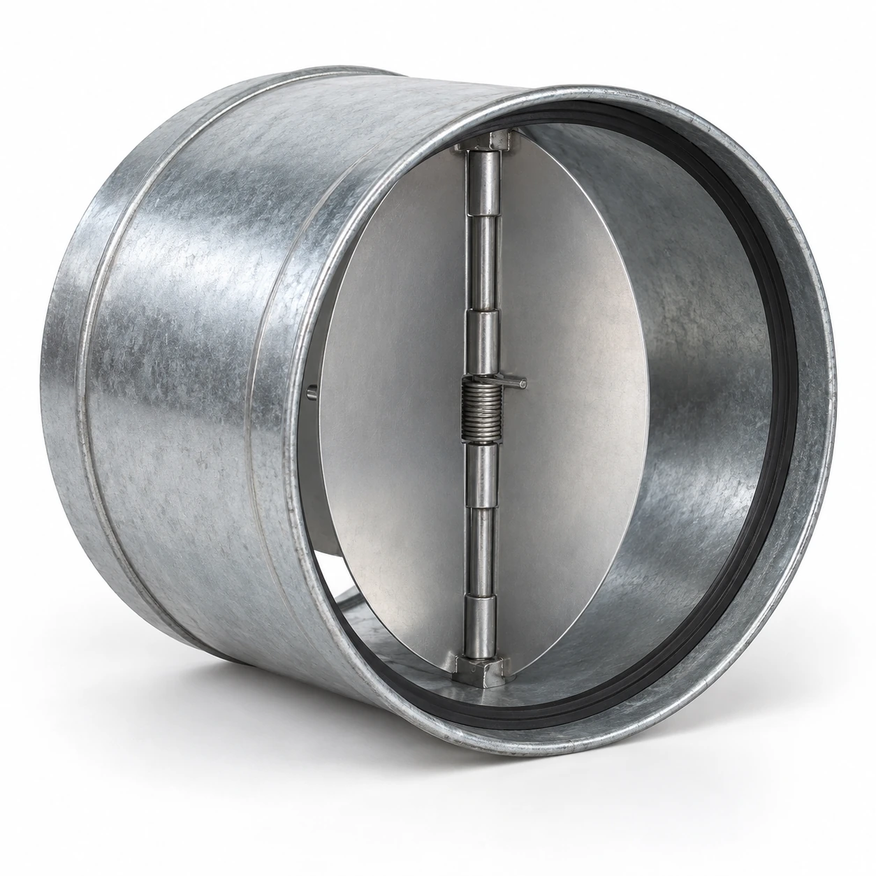
Air Volume Control Dampers
round backdraft dampers
| Nominal circular duct Ø | 100, 125, 150, 200, 250 or 315 mm |
|---|---|
| Body form | Short circular insert collar; flanged circular constructions for other connection duties |
| Body / leaves | Galvanized steel collar with aluminum leaves for the compact spring-assisted construction |
| Closing mechanism | Twin-leaf spring-assisted or single-blade gravity arrangement, selected separately |
| Sealing | Perimeter gasket and blade-edge contact matched to the selected materials and leakage duty |
| Installation fit | Collar outside diameter, body length, joint engagement and blade travel shown on the final drawing |
| Operating duty | Required volume flow, pressure loss, start-open behaviour and reverse pressure |
Nominal Ø is the duct connection size, not a guaranteed collar outside diameter or free opening. Inch-based and metric ranges are separate systems. Body length and installation orientation vary with the selected mechanism.
Round damper diameter, collar connection, blade arrangement and sealing materials can be customized for the duct system and operating conditions.
Round backdraft dampers fit circular ventilation connections and provide a compact barrier against reverse airflow. Common constructions use two spring-assisted butterfly leaves or a single circular blade, with different requirements for orientation, opening pressure and space around the moving parts.
A nominal diameter does not describe the whole fit
The nominal duct size identifies the connection family. The collar outside diameter determines whether a particular insert fits the duct or connector. The clear opening is smaller because the frame, hinge and blade arrangement occupy part of the passage. Keeping these dimensions separate avoids ordering a damper that has the right label but the wrong interface.
Identify whether the damper sits inside a duct, joins between two connectors or bolts to a flange. Confirm the available straight length and the position of nearby joints. A short body can still need additional space for an open blade, a spring or the connector used to retain it.
Two butterfly leaves
A compact twin-leaf design divides the circular opening into two semicircular moving sections. A spring can assist closure as airflow falls. Each leaf needs clearance from the collar and its neighbour, while the central hinge and perimeter gasket remain accessible for inspection.
Spring assistance affects opening resistance. A mechanism that closes positively may need more forward pressure than a lightly balanced gravity blade. Check its behaviour at the minimum intended airflow, particularly where the fan operates at reduced speed for long periods.
A single circular blade
A single-blade design can use gravity or a counterbalancing arrangement to control movement. Its pivot position and blade travel differ from the twin-leaf construction, so it may need a different installation envelope even at the same nominal diameter.
The appropriate design depends on pressure, orientation, available space and the required closing behaviour. A compact insert and a larger flanged industrial unit should not be treated as interchangeable simply because their duct diameters match.
Keep the sleeve round and the blade path clear
Over-tightened connections or misaligned ductwork can deform a thin circular collar. A small change in shape may cause one leaf to rub or prevent the edge from seating. Support the surrounding duct, use the intended connector and keep fasteners outside the moving envelope.
Flexible duct should not be left hanging from the damper as its only support. The connection needs to retain the assembly without crushing the sleeve, and the installation needs enough access to inspect both leaves. Coordinate these details with the Ventilation Ductwork arrangement before the ceiling or service enclosure is completed.
Check the direction at the actual location
The blades must open with the intended airflow. In an exhaust run, the location relative to the fan determines whether the damper opens toward the fan or toward the discharge. The desired direction is a property of the system, not simply the more convenient end of the collar.
Spring-loaded construction does not automatically permit every rotational orientation. Follow the specific hinge and mounting requirements. Leave clearance from elbows, transitions, screens and the fan inlet so local disturbances and nearby components do not obstruct the mechanism.
Commissioning should include the normal and lowest operating fan settings, then a stop-and-close check. Confirm that the blades travel freely and return as intended. If closure is incomplete, inspect the sleeve shape, gasket, hinge and installation orientation before changing any spring setting.
Allow for resistance when selecting the fan
A round damper adds resistance to the air path. That loss must be considered alongside the duct, fittings and terminal, using data relevant to the selected size and mechanism. A damper with a larger nominal diameter may reduce some losses but also needs suitable transitions and space; it is not automatically the right correction for inadequate airflow.
For replacement work, record the original duct size, measured connection dimensions and the symptom being corrected. If the problem appears only at low speed, include that condition in the selection. Replacing a failed insert with another of the same diameter can repeat the fault if the original opening pressure or mounting arrangement was unsuitable.
Round damper diameter, collar connection, blade arrangement and sealing materials can be customized for the duct system and operating conditions.