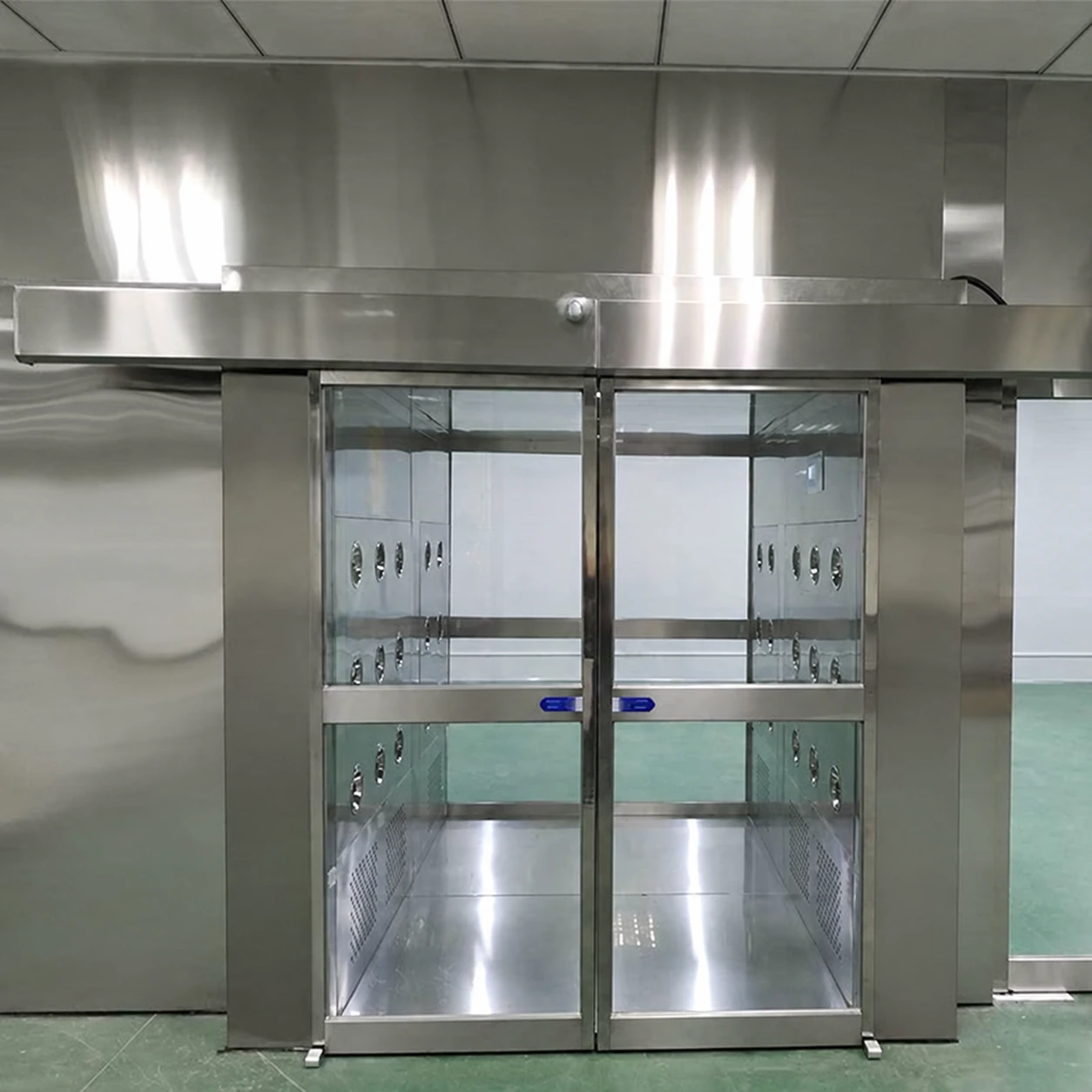
industrial cleanroom air shower
Product specifications
| Spec | Configuration |
|---|---|
| Industrial entry format | Individual personnel chamber or extended opposing-jet entry lane. |
| Outside W × D × H | Compact reference: 1400 × 1000 × 2100 mm. Extended reference: 1400 × 2000 × 2100 mm. |
| Inside clear W × D × H | Compact: 800 × 910 × 1980 mm. Extended: 800 × 1910 × 1980 mm. |
| Enclosure options | Full stainless steel, or coated exterior with stainless interior; accessible lower surfaces and replaceable door seals. |
| Filtration circuit | Accessible prefilter with a documented HEPA final-filter option; return grilles positioned outside the standing obstruction zone. |
| Jet arrangement | Opposing side banks; outlet spacing matched to individual or group standing positions. |
| Shift-entry control | Programmable shower sequence, interlocked doors and visible cycle state; occupancy detection optional. |
| Electrical connection | Voltage, phase and frequency configured for the site supply; accessible isolation provision. |
| Maintenance access | Filter and blower removal route coordinated with the workshop side and cleanroom partition. |
Reference dimensions for layout planning. Final sizes and door openings follow the approved configuration drawing.
Chamber length, nozzle coverage and service access can be configured for the installation space, shift traffic and industrial process.
A clean production area can share a building with machining, packing and maintenance. The entrance is where those different working conditions meet.
Keep workshop traffic outside the clean production route
An operator walking from a general workshop can carry loose dust on sleeves, footwear and pockets. An industrial cleanroom air shower adds a controlled stop before that operator enters the cleaner area. Filtered jets disturb loose surface particles; the return airflow carries released particles towards the filtration system. The useful result is an organised entry step that supports the gowning and housekeeping programme.
The cabinet should follow a change area, rather than stand beside an uncontrolled production door. Remove dirty outer clothing and unsuitable personal items first. Otherwise, increasing the shower time can simply expose more of a heavily contaminated garment without addressing the source of the dirt.
Build around the actual shift
Repeated entry during assembly
A short, clear one-person route suits small teams entering throughout the day. Place the controls where gloved users can see the cycle state. Door closers and seals deserve as much attention as the fan: a door that needs several attempts to latch disrupts every entry.
A queue at shift change
A longer chamber can provide more standing space, but users must not shield each other from the jets. Establish the intended occupancy and standing positions together. Compare a longer cabinet with parallel single-person lanes before giving up the changing-room floor space to a tunnel.
Dust from nearby operations
Prefilters can load rapidly if the entrance draws air from a dirty corridor. Upstream housekeeping and separation reduce that burden. Keep the return grilles clear of shoes, bags and cleaning equipment; restricted return flow can weaken the jet circuit even when the blower is running.
Cabinet size versus usable space
These reference dimensions, in millimetres, show how a cabinet envelope differs from the space available to an operator. Final dimensions follow the approved configuration drawing. Door swing and filter removal clearance are additional.
| Entry arrangement | Outside W × D × H | Inside clear W × D × H | Planning focus |
|---|---|---|---|
| Compact opposing jets | 1400 × 1000 × 2100 | 800 × 910 × 1980 | One controlled standing position near a small production room |
| Extended chamber | 1400 × 1500 × 2100 | 800 × 1410 × 1980 | More longitudinal space; assess body shielding before assigning occupancy |
| Long entry chamber | 1400 × 2000 × 2100 | 800 × 1910 × 1980 | A defined multi-position sequence with a larger changing-area footprint |
The 800 mm internal width is not the door opening. A reference clear doorway of 760 × 1960 mm is narrower and lower, so a cabinet that fits the room may still be unsuitable for a trolley or a particular access requirement.
Reliable use after installation
Establish a baseline for door closure, jet airflow, filter condition and cycle operation when the equipment is commissioned. Later, a noisy fan, longer queue or drifting door seal can be compared with that baseline. Filter changes should follow the equipment condition and site procedure, with access and cleaning arranged in advance.
For electronics assembly, precision parts or controlled packing, the right arrangement is the one that fits both the contamination route and everyday working habits. It does not replace process extraction, footwear control or the cleanroom ventilation system.
Custom configurations are available to suit the installation space, shift traffic and industrial application.