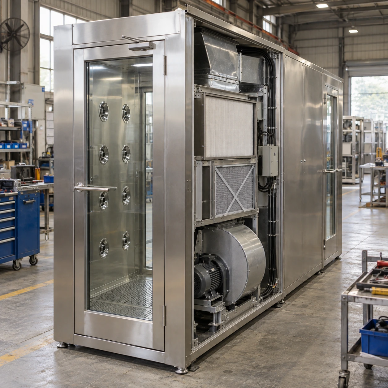
air shower system
Product specifications
| Spec | Configuration |
|---|---|
| System arrangement | Return-air, prefilter, blower, final-filter and nozzle circuit coordinated with the entry doors. |
| Outside W × D × H | Compact reference: 1400 × 1000 × 2100 mm. Extended reference: 1400 × 1500 × 2100 mm. Long reference: 1400 × 2000 × 2100 mm. |
| Inside clear W × D × H | Compact: 800 × 910 × 1980 mm. Extended: 800 × 1410 × 1980 mm. Long: 800 × 1910 × 1980 mm. |
| Final filtration | Documented HEPA option, correctly seated in a serviceable housing; filter selection coordinated with the blower duty. |
| Air distribution | Side jet banks and return locations matched to the chamber and intended standing positions. |
| Operating controls | Closure detection, programmable exposure and release sequence; visible status and optional occupancy sensing. |
| Optional interfaces | Access-control or building-management signals, with controller responsibilities defined for the project. |
| Room and power connections | Site-matched voltage, phase and frequency; cabinet sealing and any air interface coordinated with room ventilation. |
| Service indications | Optional filter-condition indication; access to fans, filters and door-control components for fault diagnosis. |
Reference dimensions for layout planning. Final sizes and system interfaces follow the approved configuration drawing.
The air circuit, door controls and chamber layout can be coordinated for the installation space, traffic and room interfaces.
The jets are the visible part. A working system also needs an unobstructed return path, correctly seated filters, coordinated doors and a clear response when something fails.
Follow the air, then follow the operator
Return and prefiltration
Released particles must leave the occupied space. Return grilles lead air back towards the filtration circuit; prefilters protect downstream components from part of the incoming dust load. A return blocked by a bag or a floor mat changes the circuit even though the nozzles remain visible.
Blower and final filtration
The blower drives air through the filter and distribution system. A correctly selected fan has to work against circuit resistance. A high motor rating alone does not establish useful airflow at the garment. Final-filter seating and seals matter because bypass airflow can avoid the intended filter media.
Plenum and jets
The supply plenum distributes air to the outlets. Nozzle direction and operator position determine which surfaces are reached. Strong airflow close to one nozzle does not establish equal coverage throughout a long chamber.
Door sequence
The control system coordinates entry closure, shower operation and clean-side release. Doors that appear closed but fail to latch need attention; repeatedly bypassing a troublesome contact defeats the intended routine.
Connect the cabinet to the room deliberately
Many air showers recirculate air within their own filtration circuit. That circulation is distinct from the ventilation that maintains the cleanroom pressure relationship. A vigorous jet circuit cannot be taken as evidence that the adjoining rooms are correctly pressurised.
Room interface
Coordinate wall seals, any make-up or relief air path and the opening sequence with the room ventilation design. Evaluate door operation with the surrounding rooms running, because a closed-cabinet check cannot show what happens during actual entry.
Control interface
Access control, occupancy sensors, alarms and a building-management connection are possible additions. Define which system owns each decision. If two controllers independently command the same door, the resulting sequence can be confusing or unsafe.
Three spaces, three distribution reviews
Reference planning sizes in mm are shown below. Final internal clearances depend on the selected construction. Longer layouts require their own nozzle and return arrangement.
| System envelope W × D × H | Internal clear W × D × H | What changes in the review |
|---|---|---|
| 1400 × 1000 × 2100 | 800 × 910 × 1980 | Coverage around one standing position, two doors and short return paths |
| 1400 × 1500 × 2100 | 800 × 1410 × 1980 | Additional longitudinal outlet positions and the effect of occupancy |
| 1400 × 2000 × 2100 | 800 × 1910 × 1980 | Distribution along the chamber, detection coverage and more complex traffic timing |
Diagnose the symptom before changing the timer
If operators report weak jets, check blocked returns, filter loading, supply distribution and fan operation before extending the shower time. If the clean-side door will not release, examine the sequence state, door contacts and lock rather than assuming a fan problem. If the corridor queue grows, measure the full entry cycle, including walking and door closure; the timer may be only one part of the delay.
Recording the original settings and component references makes those checks practical. Optional indicators can help maintenance teams recognise a changing filter condition, but their meaning and alarm response should be agreed during commissioning.
Custom configurations are available to suit the installation space, traffic and application, with filtration, door controls and room interfaces considered together.