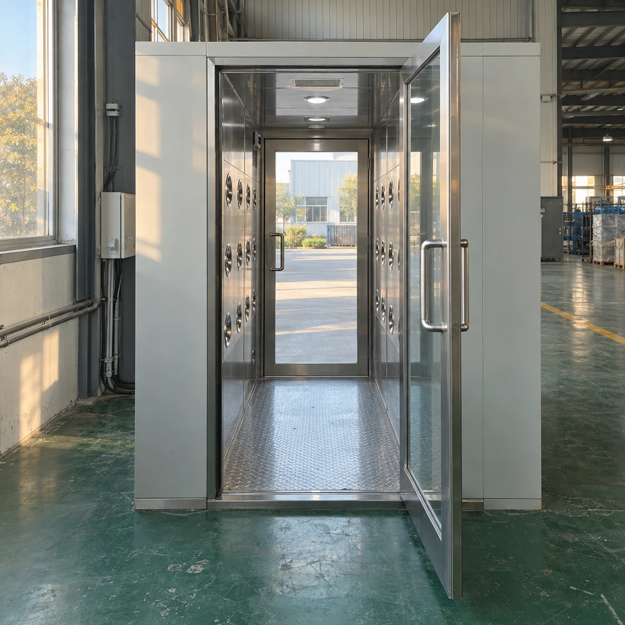
straight through air shower
Product specifications
| Spec | Configuration |
|---|---|
| Passage layout | Aligned entrance and exit on opposite ends; normal incoming and outgoing behaviour defined separately. |
| Outside W × D × H | Short reference: 1400 × 1000 × 2100 mm. Longer reference: 1400 × 1500 × 2100 mm. |
| Inside clear W × D × H | Short: 800 × 910 × 1980 mm. Longer: 800 × 1410 × 1980 mm. |
| Clear doorway reference | 760 × 1960 mm W × H for the listed cabinet references; door swing clearance additional. |
| Door choices | Manual hinged doors; powered alternatives where required by the approach space and handling routine. |
| Air delivery | Opposing filtered jets with return openings kept clear of the operator's standing position. |
| Closure and release | Door interlock, closure sensing, programmed exposure and clean-side release; emergency behaviour agreed for the installation. |
| Construction | Stainless interior or full stainless enclosure, with cleanable door frames and accessible seals. |
| Power and servicing | Site-matched electrical supply; filter access arranged independently of the through passage. |
Reference dimensions for layout planning. Final dimensions, door handing and clear openings follow the approved configuration drawing.
Door orientation, chamber depth and release sequence can be adapted to the aligned corridor, personnel movement and cleanroom entrance.
Enter from one end, complete the cycle and leave through the opposite door. A straight route makes personnel movement easy to understand when the corridor and cleanroom entrance line up.
Opposite doors need more than a straight floor plan
A straight through air shower removes the turn inside the chamber. This helps when a worker needs to stand without twisting between offset doors or when the entry route already follows a clear axis. However, opposite openings also create a direct connection between the two areas if both doors are open. An interlock and a defined operating sequence are therefore central to the arrangement.
- Approach. Complete the required gowning before reaching the entry door. Keep the waiting position out of its swing.
- Close. The entrance must latch correctly before the shower begins. A door contact detects position; it should not be assumed to prove that every seal is sound.
- Stand. Leave the jet outlets and return grilles unobstructed. The operator may need a specified turning movement to expose garment surfaces.
- Release. After the programmed sequence, the clean-side door permits entry. Departure or emergency behaviour is defined separately from the normal incoming cycle.
The space beyond each door matters
A compact cabinet can still block a narrow lobby if its entry leaf opens into the queue. The clean-side door must also clear a nearby wall, bench or adjacent cleanroom door. Mark both full door swings on the drawing; do not assess fit with the doors closed.
Sliding or automatic doors change the space requirement and control sequence. They can remove a swing conflict, but introduce drive equipment, sensing zones and surfaces that need cleaning. Choose them to solve a defined access problem rather than treating automation as a universal upgrade.
Reference straight layouts
W × D × H, mm; outside cabinet followed by inside clear dimensions. These are space-planning references.
- Short route
- Outside 1400 × 1000 × 2100
Inside 800 × 910 × 1980
Use where a single standing position and two door approaches can fit. - Longer dwell space
- Outside 1400 × 1500 × 2100
Inside 800 × 1410 × 1980
Useful where the cycle arrangement requires more front-to-back room. - Extended route
- Outside 1400 × 2000 × 2100
Inside 800 × 1910 × 1980
Evaluate spacing between operators and the resulting queue pattern.
When a turn is the better choice
If the cleanroom door sits at the side of the lobby, forcing a straight cabinet into place can waste space or move the clean entrance into a busy circulation path. An angled route may be more useful. The choice should follow the room interfaces and desired direction of travel; a straight cabinet is not automatically the smallest overall installation.
For two-way traffic, prevent incoming staff and outgoing staff from meeting inside the chamber during a normal entry cycle. A controlled outward passage, a separate exit or a scheduled sequence can address this, depending on the facility. A longer chamber alone does not resolve opposing movement.
Before ordering, distinguish the inside passage from the clear doorway. A 760 × 1960 mm reference opening on an 800 mm-wide chamber is a separate restriction. Check access needs and local egress requirements alongside the cleanroom workflow.
Door orientation, chamber length and operating sequence can be customised to suit the installation space, traffic and application.