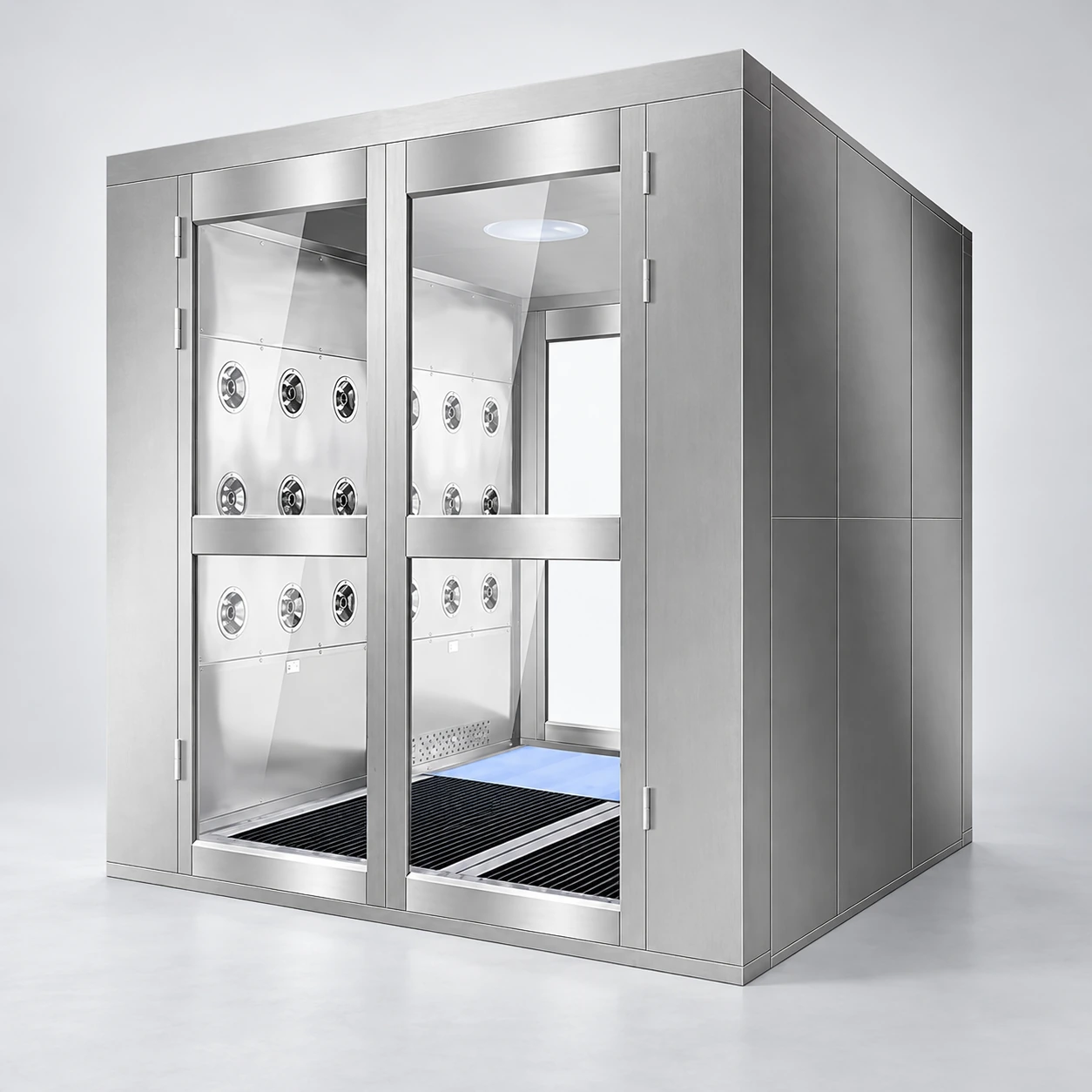
personnel air shower
Product specifications
| Spec | Configuration |
|---|---|
| Personnel-entry type | Air shower for clothed operators, with an optional integrated shoe-sole cleaning stage. |
| External reference sizes | Compact entry: 1400 × 1000 × 2100 mm Deeper chamber: 1400 × 1500 × 2100 mm Extended chamber: 1400 × 2000 × 2100 mm W × D × H reference layouts; final dimensions follow the approved configuration drawing. |
| Wearer clearance | Internal clear width, headroom and door opening selected for the garments, users and required turning movement. |
| Clothing coverage | One-sided or opposing-side jet banks; upper blowing considered where suitable for hood surfaces and comfort. |
| Floor option | Standard chamber floor or an integrated sole-cleaning arrangement with its own cleaning and maintenance requirements. |
| Interior finish | Stainless cleaning surfaces with accessible lower return areas. |
| Particle filters | Accessible prefilter and documented final filter matched to the blower and selected jet coverage. |
| Door and user controls | Manual or automatic doors, gloved-hand control access, visible countdown and emergency release. |
| Traffic configuration | Defined standing positions and group sequence based on the full entry-to-exit cycle. |
Chamber access, garment coverage and footwear provisions can be configured for your personnel routine and shift traffic.
Give a clothed operator enough space to stand, turn, understand the signals and leave comfortably.
The wearer is the design reference.
A personnel air shower addresses particles on the outer garment during entry. Its working space should be assessed with the actual clothing ensemble, not with an unoccupied chamber. Hoods, coveralls, sleeves and footwear affect how the wearer turns, sees the countdown and reaches a release control.
The operator should not need to lean against walls or stand in a doorway to avoid the nozzles. A comfortable posture leaves the intended garment surfaces exposed and makes the procedure repeatable. People carrying trays or tools need a separate decision: the item can shield the garment and complicate door operation.
Jet positions
Side nozzles at different heights cover different garment areas. Opposing-side blowing is an option where the footprint permits it; a one-sided arrangement needs an appropriate turning procedure. Top blowing may be considered for upper surfaces when compatible with the hood and user comfort.
Door use
Manual doors need usable handles and predictable closer action. Automatic swing or sliding doors can reduce contact, but detection and obstruction sensing must suit people in cleanroom clothing. Avoid a sensor layout that reacts to the queue outside as though the chamber were empty.
Information and release
Use clear cycle status and door indications. Place controls where a gloved wearer can reach and identify them. Emergency release and loss-of-power behaviour should be included in the agreed sequence rather than discovered during a fault.
More people require more than a longer timer.
For planning, compare 1400 × 1000 × 2100 mm, 1400 × 1500 × 2100 mm and 1400 × 2000 × 2100 mm external W × D × H envelopes. These configuration planning examples illustrate increasing depth, not certified user capacities. Dimension internal clear width and the door opening separately, then lay out the intended standing positions.
If the users require wider access, consider a wider chamber drawing rather than relying on an external width figure. Approach space, manoeuvring clearance and the full route through the changing area matter as well.
Count arrivals at the peak.
A planning calculation is available positions × 60 ÷ full cycle seconds for nominal people per minute. Include entry, closing, shower, release and exit in the full cycle. The result is an upper planning value, not demonstrated throughput; waiting, unfamiliar users and opposing traffic reduce it.
Custom configurations can suit the installation space, wearer needs, shift traffic and application.