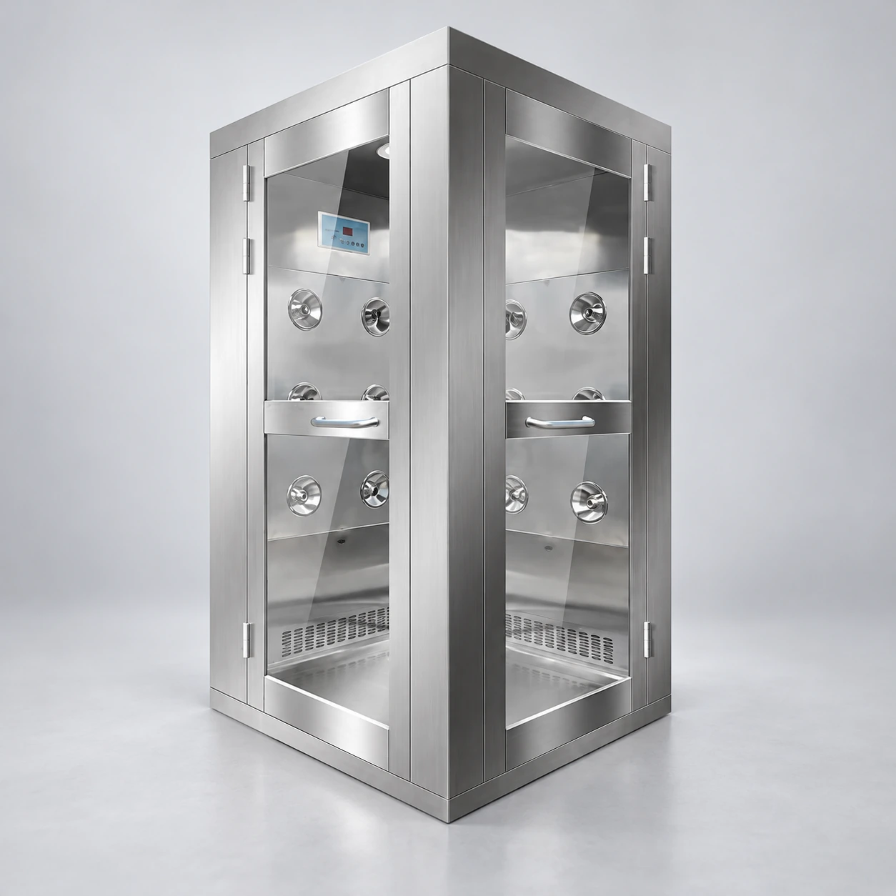
air shower for cleanroom
Product specifications
| Spec | Configuration |
|---|---|
| Personnel exposure | Single-sided or opposing jets, coordinated with the garments and prescribed standing movement. |
| Outside W × D × H | One-sided reference: 1200 × 1000 × 2100 mm. Opposing reference: 1400 × 1000 × 2100 mm. Extended reference: 1400 × 1500 × 2100 mm. |
| Inside clear W × D × H | Compact references: 800 × 910 × 1980 mm. Extended reference: 800 × 1410 × 1980 mm; standing positions defined for the chosen layout. |
| Door layout | Straight or turning route, with the incoming sequence and normal departure behaviour specified. |
| Nozzle settings | Outlet angle and height matched to exposed garment areas; optional overhead distribution where designed. |
| Air filtration | Accessible prefilter, serviceable final-filter housing and documented HEPA option. |
| Cycle controls | Programmable duration, visible operating state, door interlock and optional occupancy detection. |
| Maintained condition | Optional filter-condition indication; retained settings and airflow measurement locations for post-service comparison. |
| Material and supply | Cleanable stainless or stainless-lined enclosure; voltage, phase and frequency matched to the installation. |
Reference dimensions for layout planning. Final dimensions and usable movement space follow the approved configuration drawing.
The chamber, jet pattern and operating sequence can be matched to the clothing, daily arrival pattern and cleanroom process.
The right air shower gives personnel a repeatable entry step. Its practical value depends on the clothing, standing movement and daily routine it serves, as well as the condition of the equipment.
Turn filtered jets into a usable garment-exposure routine
After the required changing procedure, the operator enters a controlled chamber and exposes the outer garment to filtered jets. The airflow assists with loose surface-particle removal, while the return path carries released particles towards filtration. The cabinet provides a consistent place and sequence for that action, rather than leaving it to an informal pause at the doorway.
The intended clothing matters. A close-fitting cleanroom garment, a loose work coat and a bulky hood present different surfaces to the jets. Establish the standing position and movement with the clothing actually used. Turning may improve exposure to a single-sided layout; opposing jets may make the routine easier where both sides need attention. Neither arrangement cleans areas hidden under folded fabric or replaces an unsuitable gowning procedure.
Configure the equipment for everyday entry
Usable standing space changes the routine
Reference planning dimensions below are in mm, W × D × H. Final dimensions follow the approved configuration drawing. The inside clear chamber is distinct from the doorway and outside cabinet.
Single-sided movement
1200 × 1000 × 2100 outside
800 × 910 × 1980 inside clear
Review whether the prescribed turning movement is comfortable in the gown and footwear used. A smaller equipment width is useful only if that movement remains practical.
Opposing-jet position
1400 × 1000 × 2100 outside
800 × 910 × 1980 inside clear
Set a position that exposes both sides while leaving the outlets and returns unobstructed. The wider envelope houses equipment rather than adding interior width.
Extended exposure space
1400 × 1500 × 2100 outside
800 × 1410 × 1980 inside clear
Check how users occupy the longer space. Extra length must not encourage close standing that shields one garment behind another.
Establish a useful operating baseline
Commissioning brings the selected configuration and the real entry routine together. Confirm that the doors close reliably, the outlets reach the intended positions and the controls follow the agreed sequence. Record the airflow measurement locations and settings so later maintenance can identify a meaningful change. An outlet reading describes the air circuit; any garment-removal assessment needs a separate method suited to the process.
The full visit matters to staff. Walking in, closing the door, completing the movement and leaving can take longer than the fan-on period. If the route routinely queues, review the arrival pattern and whole sequence before shortening exposure arbitrarily. The aim is an entry step that staff can follow consistently under normal working conditions.
Restore the cause when performance changes
Weak jets can result from loaded filters, blocked returns or a distribution fault. A stalled sequence can result from a door contact or latch problem. Repeated nuisance alarms can cause users to ignore a genuine abnormal condition. Diagnose the changing behaviour and restore the original function; simply extending the timer or bypassing an interlock leaves the cause in place.
After filter replacement or repair, restore nozzle positions, seals and control settings, then return to the agreed entry procedure. Clear component references and retained baseline information make that process easier for the next maintenance team.
Custom configurations are available to suit the installation space, personnel traffic and cleanroom application, with the operating routine developed around the garments and process.