Ultrasonic Cleaners
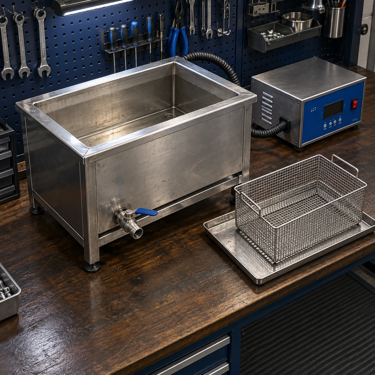
ultrasonic cleaner tank
| Internal tank W × D × H (mm) | 600 × 450 × 450 / 1000 × 500 × 400 / 750 × 650 × 500 |
|---|---|
| External W × D × H (mm) | 780 × 550 × 800 / 1180 × 600 × 800 / 930 × 750 × 800 options, respectively |
| Ultrasonic frequency | 25 or 40 kHz, selected for the cleaning task |
| Nominal ultrasonic power | 1–2 kW across the listed tank families; generator matched to transducers |
| Heating / control | 4.8–7.2 kW options; thermostatic control up to 80 °C |
| Tank / frame | Welded stainless tank; 304 or 316L wetted construction selected for the solution |
| Loading / bath care | Suspended basket and lid; optional basket lift, filtration, oil separation and rinse stage |
| Electrical / discharge | 400 V three-phase, 50/60 Hz configuration; drain and overflow connection by tank design |
Listed cabinet envelopes apply to complete floor units. An integration tank or replacement vessel requires its own mounting, transducer and connection drawing.
Tank geometry, mounting interfaces, wet materials and generator arrangement can be configured for the intended cleaning station.
An ultrasonic cleaner tank is an acoustic assembly, not simply a stainless vessel with a heater. The tank wall, transducer arrangement and generator must work together to transfer energy into the cleaning liquid and the loaded work area.
Complete tank assembly
A new wash station can use a tank supplied with its matched ultrasonic system, heaters where required, liquid connections and basket supports. The integration boundary should identify which controls, protection devices and accessories belong to the tank package and which are supplied by the line builder.
Replacement tank
A leaking or worn vessel cannot be replaced on external dimensions alone. The existing generator, transducer type, mounting arrangement and electrical connections need to be checked together. Reusing an unmatched generator can leave the new assembly poorly driven or damaged.
The wet geometry controls everyday use
A practical tank has accessible corners and a discharge arrangement that lets the operator remove accumulated debris. A sloping bottom can assist draining, but the low point and attached outlet also change the installation envelope. Overflow pockets and fittings explain why a catalogue's total capacity may differ from a simple multiplication of the main cavity dimensions.
The rim and basket supports must keep the work off the vibrating bottom. For heavy loads, use a properly designed supporting frame and lifting system rather than relying on thin sheet-metal edges. Make room to remove the basket without fouling a hood, overhead pipe or lid.
Choose wetted materials as a system
Consider the tank, drain valve, seals, heater surfaces and any filter housing exposed to the liquid. Selecting a stainless grade for the vessel does not automatically make every connected component compatible with the cleaning solution. Chemistry, concentration, temperature and exposure time all matter.
Ordinary aqueous tanks are not a substitute for purpose-engineered solvent equipment. If the process depends on a volatile flammable liquid, the equipment specification must be reconsidered before procurement.
Useful information for a tank enquiry
Provide a section drawing showing the working level, basket and largest component; identify available electrical supply, drain route and maintenance access. For a replacement, include the generator and transducer identification as well as the old tank dimensions. The stainless ultrasonic cleaner page discusses material and surface care in more detail.
Tank geometry, mounting interfaces, wet materials and generator arrangement can be configured for the intended cleaning station.