Ultrasonic Cleaners
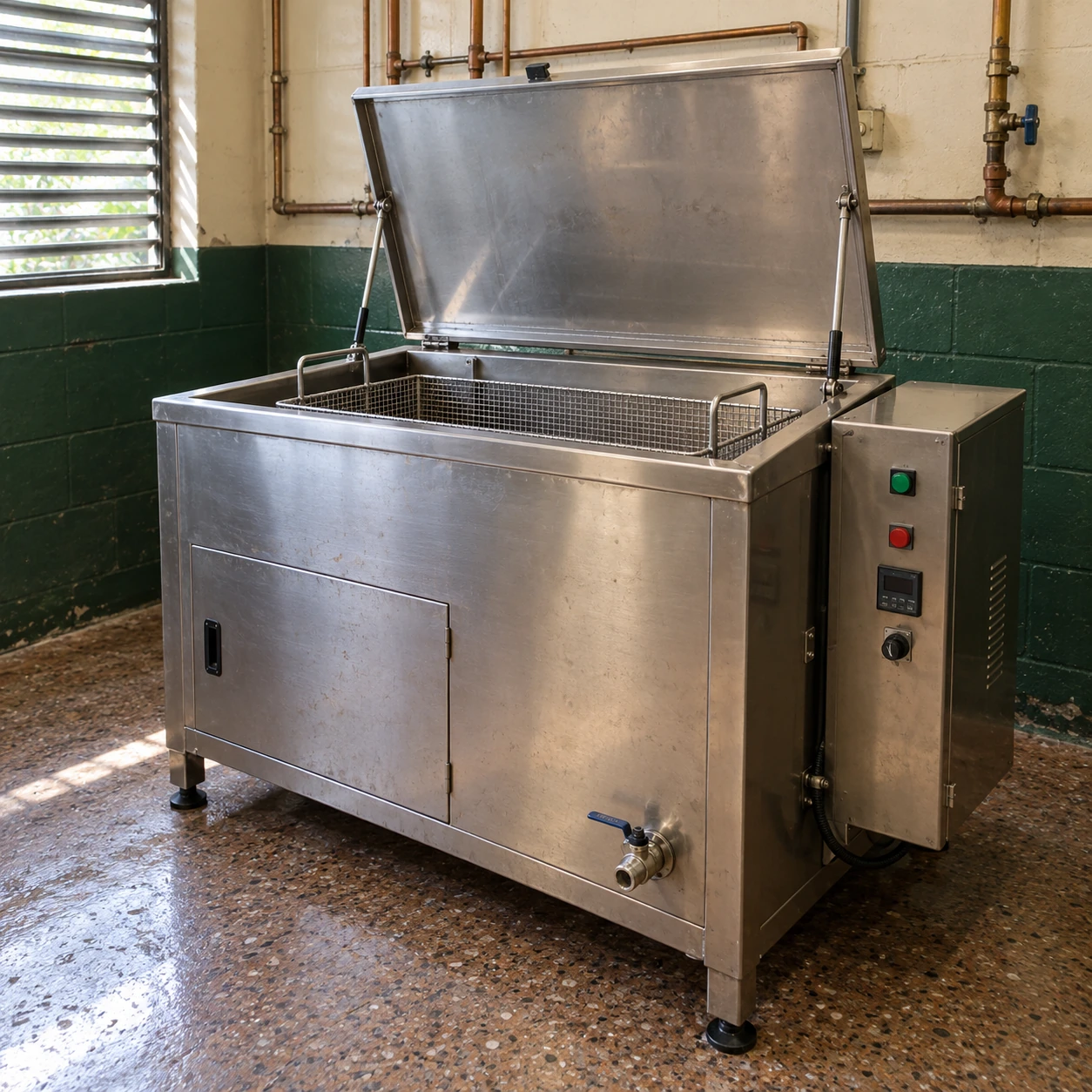
ultrasonic cleaner machine
| Internal tank W × D × H (mm) | 600 × 450 × 450 / 1000 × 500 × 400 / 750 × 650 × 500 |
|---|---|
| External W × D × H (mm) | 780 × 550 × 800 / 1180 × 600 × 800 / 930 × 750 × 800 options, respectively |
| Ultrasonic frequency | 25 or 40 kHz, selected for the cleaning task |
| Nominal ultrasonic power | 1–2 kW across the listed tank families; generator matched to transducers |
| Heating / control | 4.8–7.2 kW options; thermostatic control up to 80 °C |
| Tank / frame | Welded stainless tank; 304 or 316L wetted construction selected for the solution |
| Loading / bath care | Suspended basket and lid; optional basket lift, filtration, oil separation and rinse stage |
| Electrical / discharge | 400 V three-phase, 50/60 Hz configuration; drain and overflow connection by tank design |
A machine configuration combines the listed tank family with matched electrical and handling equipment. Accessories may extend beyond the cabinet dimensions.
The complete machine layout, controls and supporting accessories can be configured for your parts and installation.
An ultrasonic cleaner machine combines the wet cleaning assembly with electrical controls and practical handling. Specifying the complete machine avoids treating the tank, generator and accessories as unrelated purchases that may not work together.
What belongs in the complete machine
Wet assembly
The tank holds the liquid and supports the acoustic system. Basket supports, drain and overflow provisions shape how the work is loaded and how the bath is maintained.
Energy and control
The generator drives the matched transducers. Heating, time control and any auxiliary pump have their own roles and electrical demand.
Handling and enclosure
The lid, basket, frame and service panels make the assembly usable. They need clear movement and access in the actual installation.
Connected power needs a complete account
Ultrasonic power is not the same as the machine's total connected load. Heaters can account for a substantial share, and filtration or lifting equipment adds further demand. Use the final electrical schedule when planning the site supply.
A cabinet with a digital display does not necessarily include data recording, a programmable controller or a line interface. List these functions explicitly if they are needed, together with responsibility for connecting them to the existing system.
Provide room to operate
Check the open lid, raised basket and operator position. Keep the incoming carrier and clean receiving area separated so that work can move through the process without backtracking.
If the basket is heavy, the machine scope should include a suitable handling proposal rather than leaving operators to improvise a lifting method.
Provide room to service
Locate electrical panels, generator cooling and liquid connections where they remain accessible after installation. A drain hidden behind another tank is difficult to use even if it is present on the specification.
Keep the approved equipment drawing and component identification available for maintenance and replacement-part enquiries.
Confirm the process as well as the hardware
A complete machine can be mechanically correct while the cleaning method still needs development for a particular part. Evaluate the solution, loading pattern, cycle and finishing stages against the required result. Cleaning quality should be checked on representative work after rinsing and drying.
If only the vessel is required for integration or replacement, the scope differs from a complete machine; see ultrasonic cleaner tank. State this boundary clearly when requesting supply.
The complete machine layout, controls and supporting accessories can be configured for your parts and installation.