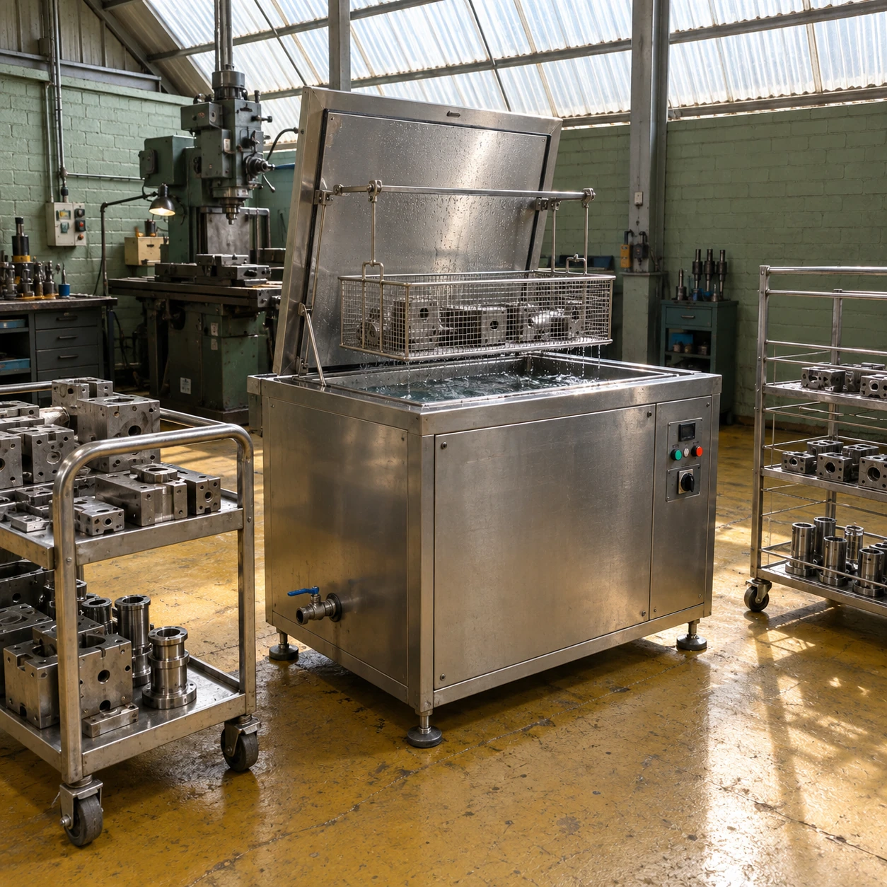
Ultrasonic Cleaners
ultrasonic cleaner industrial use
| Internal tank W × D × H (mm) | 600 × 450 × 450 / 1000 × 500 × 400 / 750 × 650 × 500 |
|---|---|
| External W × D × H (mm) | 780 × 550 × 800 / 1180 × 600 × 800 / 930 × 750 × 800 options, respectively |
| Ultrasonic frequency | 25 or 40 kHz, selected for the cleaning task |
| Nominal ultrasonic power | 1–2 kW across the listed tank families; generator matched to transducers |
| Heating / control | 4.8–7.2 kW options; thermostatic control up to 80 °C |
| Tank / frame | Welded stainless tank; 304 or 316L wetted construction selected for the solution |
| Loading / bath care | Suspended basket and lid; optional basket lift, filtration, oil separation and rinse stage |
| Electrical / discharge | 400 V three-phase, 50/60 Hz configuration; drain and overflow connection by tank design |
Tank options are selected for the load and process. Operating liquid volume, basket capacity and cycle output are established separately.
The cleaning station can be configured around your industrial parts, residue and downstream process.
Industrial use starts with a process requirement: a component must leave cleaning ready for its next operation. Ultrasonic equipment can assist residue removal from accessible wetted surfaces, but the required finish determines the chemistry, loading and finishing stages.
Match the cleaning task to the next operation
After machining
Oils and fines can remain in threaded holes and recesses. Bulk chips should be removed first, and the load oriented so the liquid can enter and displaced air can leave.
Before assembly
Loose contamination can interfere with fits and movement. Rinse quality and protection from dirty handling become as important as the ultrasonic stage itself.
During maintenance
Aged deposits may need a different solution from fresh machining oil. Separate incompatible materials and assess seals, adhesives and coatings before immersing an assembled component.
A visible surface is only part of the inspection
Choose the inspection method to match the defect that matters: residual oil, particles in a passage, staining or retained detergent. A shiny outer surface does not establish that a blind recess is clean. Similarly, a vigorous-looking bath does not quantify cleaning performance.
Trial representative geometry and the normal soil burden. Keep the basket pattern consistent while evaluating a process, then investigate changed results through bath condition, loading and temperature before assuming the generator has lost power.
Integrate the station without creating a wet bottleneck
Separate incoming and outgoing carriers. Allow the basket to drain before it reaches the rinse stage, and give the part a suitable drying route. If every cleaned batch waits on one small drying rack, a larger ultrasonic tank may increase work in progress without increasing accepted output.
Filtration and oil management should be selected around what the bath receives. Dissolved substances, suspended particles and free oil are different problems and may not be removed by the same accessory.
Keep the application boundary clear
Use an aqueous cleaning formulation compatible with the equipment and workpiece. Do not assume that a successful steel-part process is also suitable for aluminium, optical coatings, bonded assemblies or electronic components. Cleaning alone is not sterilization.
For integrating a selected machine into a production cell, see industrial ultrasonic cleaner. An application enquiry is most useful when it includes the next manufacturing step and its cleanliness requirement, not only the size of the tank.
The cleaning station can be configured around your industrial parts, residue and downstream process.