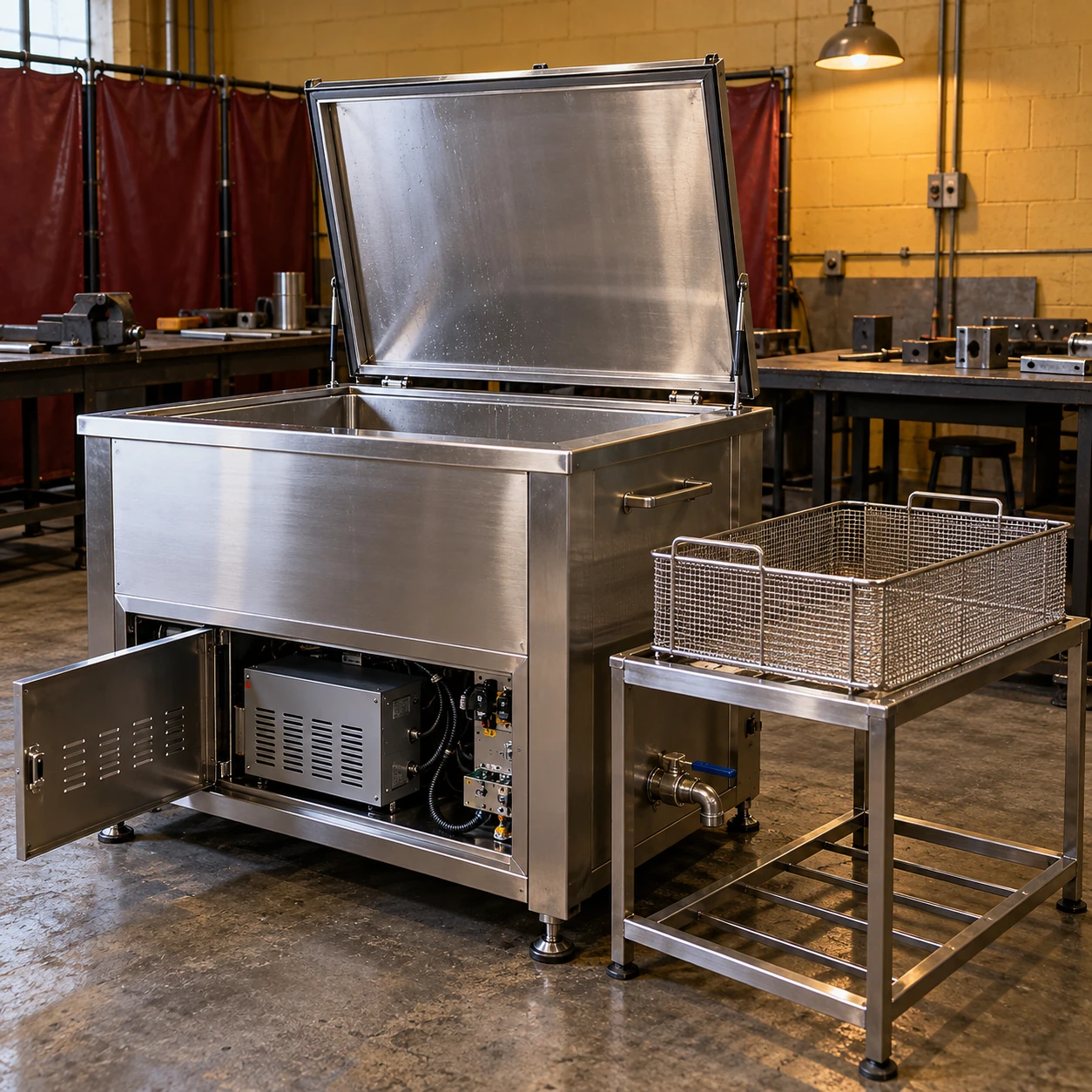
Ultrasonic Cleaners
large industrial ultrasonic cleaner manufacturers
| Internal tank W × D × H (mm) | 600 × 450 × 450 / 1000 × 500 × 400 / 750 × 650 × 500 |
|---|---|
| External W × D × H (mm) | 780 × 550 × 800 / 1180 × 600 × 800 / 930 × 750 × 800 options, respectively |
| Ultrasonic frequency | 25 or 40 kHz, selected for the cleaning task |
| Nominal ultrasonic power | 1–2 kW across the listed tank families; generator matched to transducers |
| Heating / control | 4.8–7.2 kW options; thermostatic control up to 80 °C |
| Tank / frame | Welded stainless tank; 304 or 316L wetted construction selected for the solution |
| Loading / bath care | Suspended basket and lid; optional basket lift, filtration, oil separation and rinse stage |
| Electrical / discharge | 400 V three-phase, 50/60 Hz configuration; drain and overflow connection by tank design |
These selectable configurations are not proprietary shengtongJH model ratings. Final drawings and electrical data belong to the selected supply configuration.
Tank fabrication, access layout and accessory interfaces can be specified for your application through the selected equipment supply.
A manufacturer-oriented enquiry needs construction detail as well as a tank size. shengtongJH sources industrial cleaning equipment and can organise the procurement specification around the tank, ultrasonic assembly, handling system and evidence required from the supplying manufacturer.
Tank fabrication affects both use and service
Review the wetted material, welded joints, drain position and basket support arrangement. A thick external cabinet does not reveal the construction of the vibrating tank. The relevant questions are whether the vessel suits the solution and whether the load can be supported without damaging the active surfaces.
A practical fabrication drawing should distinguish the clear cavity from overflow pockets and fittings. It should also show how heaters and transducers are accessed, since these service areas may be obstructed after installation.
Specify an acoustic assembly, not a collection of wattages
The generator drives a matched transducer system through the tank structure. Transducer arrangement, frequency and loaded geometry influence how energy reaches the liquid. Combining a larger generator with an unrelated tank is not a dependable route to improved cleaning.
Ask for the basis of each power figure. Nominal ultrasonic power, short-duration peak values and heater power describe different things. A quotation that adds them together into one headline number is difficult to compare with another machine.
Mechanical review
Confirm the load path, basket clearance, lid movement and connections on the approved drawing. Identify components that protrude beyond the cabinet.
Electrical review
Document the supply, protection arrangements and combined connected load. Include auxiliary pumps and lifting equipment where they form part of the package.
Process review
Agree a representative component, soil condition, bath condition and inspection method. An empty bath demonstration cannot establish the result for a fully loaded basket.
Make modifications traceable
If tank depth, drain location or basket geometry changes, update the associated drawing and configuration record. Such changes can alter liquid volume, installation clearance and handling. The purchase should identify the final arrangement instead of relying on a photograph of an earlier machine.
For the tank-to-generator boundary in a replacement or integration project, see ultrasonic cleaner tank. shengtongJH's role is sourcing and supply coordination; factory ownership, certification and production capacity are not implied.
Tank fabrication, access layout and accessory interfaces can be specified for your application through the selected equipment supply.