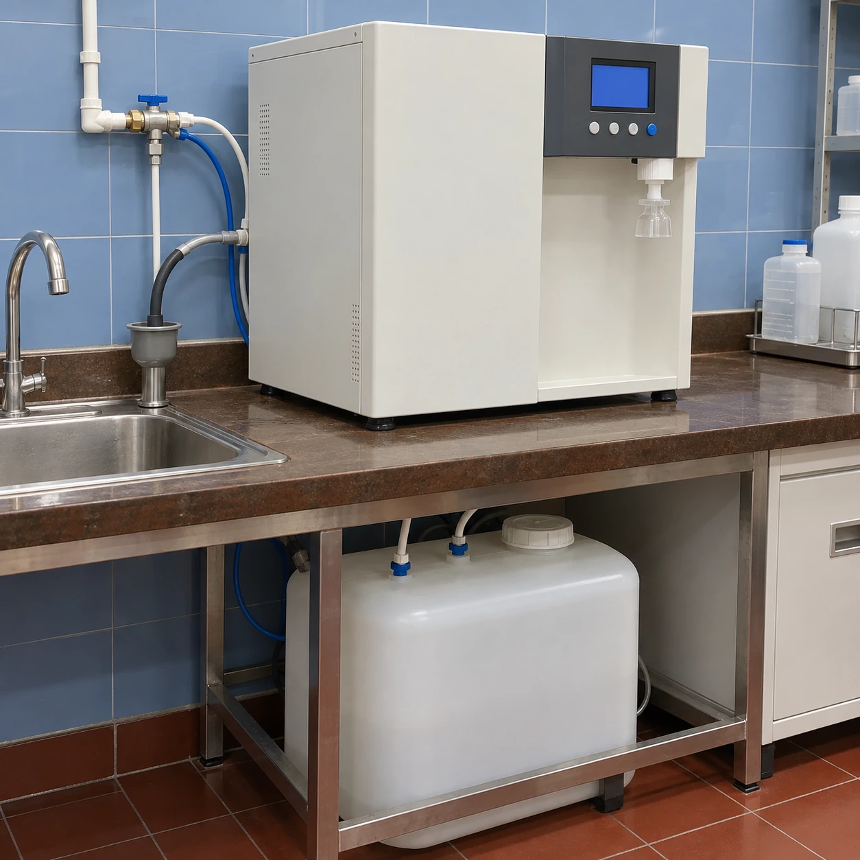
Ultrapure Water Systems
low drain ultrapure water system
| Feed arrangement | Tap-water pretreatment with RO and final polishing; prepurified-feed versions also selectable |
|---|---|
| RO production options | 3 / 6 / 12 L/h at 15°C feed temperature; feed pressure and quality affect output |
| Cabinet W × D × H (mm) | 260 × 470 × 470; 280 × 530 × 510; 305 × 400 × 545 — footprint depends on configuration |
| Storage and dispensing | 5 / 6 / 12 L storage options; up to 1 L/min intermittent ultrapure dispense with a matched unit |
| Ionic-purity acceptance | 18.2 MΩ·cm at 25°C at point of dispense, subject to the selected system and agreed feed conditions |
| Treatment options | Ion-exchange polishing; 185/254 nm UV; selected 0.2 or 0.22 μm final filter; application-specific UF |
| Water-use assessment | Feed, permeate, reject and cleaning losses assessed over the working cycle; recovery specified for the selected feed and membrane |
| Power and controls | 100–240 V AC, 50/60 Hz supply options; resistivity/temperature display, tank-level control and feed alarms |
| Installation | Benchtop or approved wall mount; separate allowance for dispenser, reservoir, tubing and service access |
There is no universal recovery percentage for these options. The selected system's water balance, feed limits, final footprint and drainage arrangement are specified together.
A low drain ultrapure water system aims to reduce the water discharged while still protecting the membrane and delivering the required laboratory water. Drain performance must be defined over a real operating cycle.
Define the water balance at the correct boundary
RO membrane recovery is the permeate volume divided by the feed volume for the same period. It describes the membrane stage. Total water discharged by an installed ultrapure system can also include startup flushing, scheduled rinsing, sanitation and water rejected during preparation for use.
A system may therefore show an attractive membrane recovery while sending more water to drain over a normal working week. Compare systems using the same feed conditions, useful-water demand and operating cycle. For a polishing-only unit, include the upstream supply when evaluating the laboratory's total water use.
Why concentrate cannot simply be stopped
The reject stream carries contaminants away from the membrane. Restricting it indiscriminately increases concentration near the membrane surface and can promote scaling or fouling. A modification that reduces the drain flow briefly can shorten membrane life or reduce useful output.
Attainable recovery depends on the membrane arrangement, feed composition, temperature, pressure and pretreatment. Higher recovery is a design decision evaluated against those conditions, not a setting to maximize without limits.
Where practical reductions come from
Match production and storage to real demand, repair leaks and use the appropriate water grade for each task. An engineered recovery or recycle arrangement may be useful where the feed allows it, but recirculating concentrate changes the load that the membrane sees.
Unnecessary final-quality water used for ordinary washing can waste both treated water and consumable capacity. Separating permitted lower-grade demand can be as relevant as changing the RO stage.
Keep reject reuse separate from reagent water
Concentrate may be suitable for a different, less demanding use after its quality and destination have been assessed. It is not ultrapure water. Any collection or reuse arrangement needs suitable identification, capacity control and protection against cross-connection or backflow. Storage creates its own maintenance requirements and should not be added merely to hide visible discharge.
The laboratory's drain must accept the expected flow, including flushing. Secure the connection and preserve the required air gap or backflow protection for the supplied arrangement. A submerged loose hose can create a contamination route even when the purification equipment is working correctly.
Ask for measured operating information
Request feed, permeate and discharge data for the proposed configuration under stated conditions. Include the periods when the system is idle or cleaning, and distinguish water produced from water accepted and used. Compare the low-drain option against measured operating conditions and your actual work cycle, including the discharge needed to protect the treatment stages.
When water reduction is part of an operating-cost decision, assess it together with membrane replacement and labour in the lifecycle comparison.
The RO arrangement, storage, monitoring and reject-water connections can be customized to your feed-water conditions and site drainage requirements.