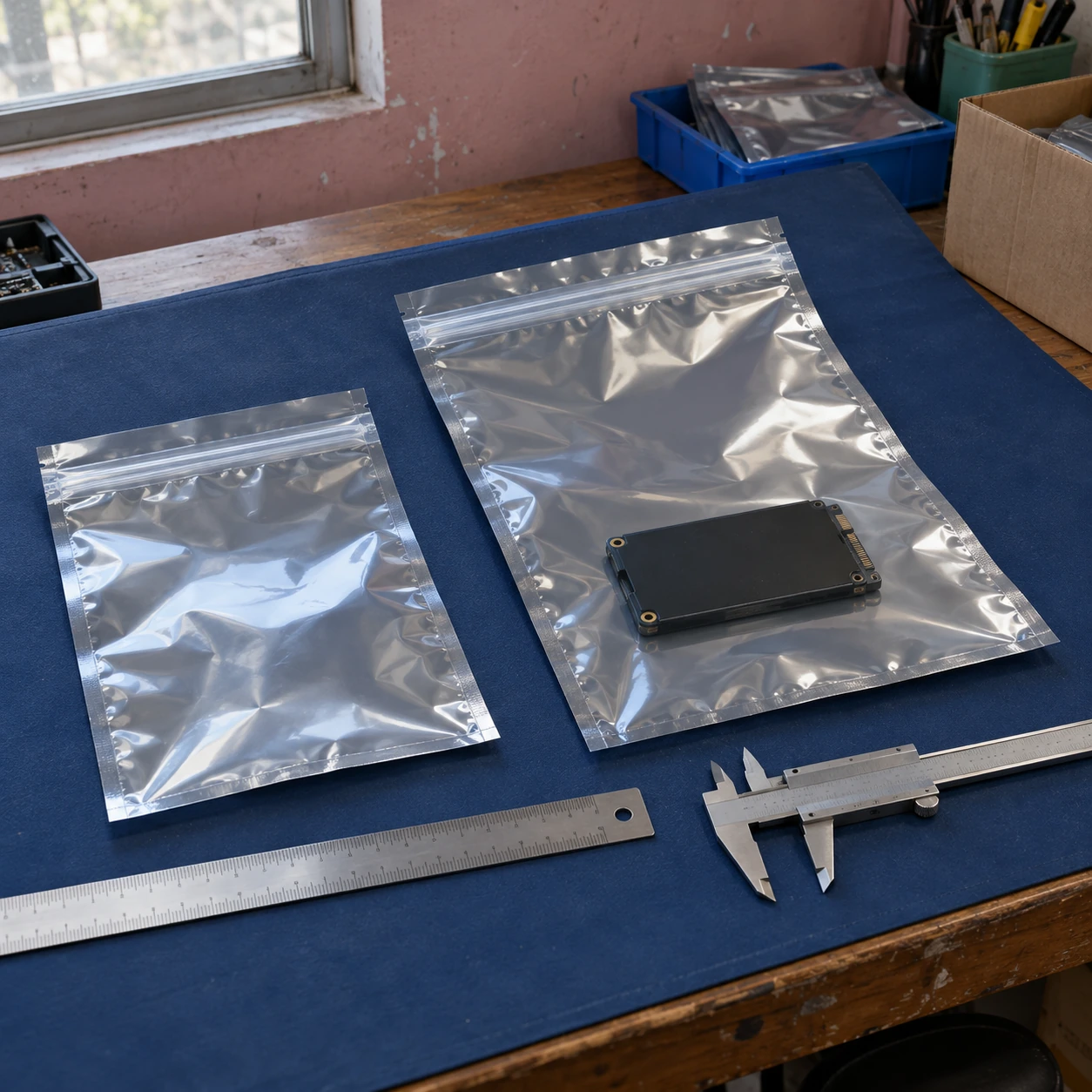
Static Shielding Bags
static shielding bags - reclosable
| Bag style | Flat metallized pouch with integrated reclosable zipper |
|---|---|
| Nominal W × L options | 127 × 203.2; 203.2 × 304.8; 254 × 355.6; 304.8 × 457.2 mm |
| Dimension definition | Nominal flat size; usable cavity, seal width and top-lip allowance agreed separately |
| Film construction | Metal-in laminate; approximately 0.071 mm common option |
| Packing variables | Assembly width, length, thickness, projections and protective insert envelope |
| Closure specification | Zipper location, clear opening and complete engagement across the mouth |
A nominal flat bag dimension is not a guaranteed internal packing dimension. Final fit follows the supplier drawing and a trial with the complete packed item.
A reclosable shielding bag must fit the assembled part, its projections and any protective insert while leaving the zipper clear. Selecting only by the board's flat outline can produce a pouch that accepts the item but cannot close reliably.
Start with the packed envelope
Measure the complete item, including terminals, mounting ears, connectors and the tray or corner protection that travels with it. A flat film pouch must bend around the item's thickness; the available face width is therefore not the same as the width of an empty flattened bag.
Decide which end enters first. A narrow board with a projecting connector may need a wider opening than its main body suggests. Rotating it can change how it passes the zipper, but rotation should not place sharp features against a seam or cause loose parts to slide into the closure.
At the mouth
The zipper needs a clear path across the entire opening. Keep components, protective inserts and labels out of that path. A pouch can appear long enough while its useful height below the zipper is too short.
The top lip provides a grip for opening. It is not additional protected storage space. Define whether the quoted length includes that lip or is measured to a closure datum, rather than assuming different suppliers use the same convention.
Along the sides
Welded margins and dimensional tolerances affect the usable cavity. Allow the laminate to settle around the item without taut corners. Do not use the seal as a handle for a heavy assembly.
If a tray is needed, trial the bag with the tray loaded. Its flange can become the widest point even when the electronic part itself has ample clearance.
Resolve fit problems at their cause
The part enters, but the zipper bows
The packed depth or height is consuming the closure allowance. Recheck the usable cavity and insert position instead of repeatedly forcing the zipper shut.
Corners leave tight impressions
Redistribute contact with suitable edge protection or a better-fitting tray. A stronger film can still be punctured when a sharp feature carries the load.
Excess film catches in the tote
Review the bag and container together. A closer fit or a controlled layout may reduce snagging without folding the package tightly around the assembly.
Approve the handling space, not just the dimensions
Have an operator pack and remove the item using the normal workstation arrangement. The useful result is a repeatable action with no stretching, dragging or trapped material. Then place the closed pouch into its transport tray or carton and check whether the surrounding packaging presses on the closure.
Record the accepted bag drawing with the part or packing instruction. This turns a successful sample into a repeatable order instead of relying on a nominal size that can mean different things across product ranges. Manufacturing specification details cover the material and conversion decisions behind that drawing.
The usable cavity, zipper location, bag dimensions and marking can be customized around the complete packed assembly.