Smoke Detectors & Alarms
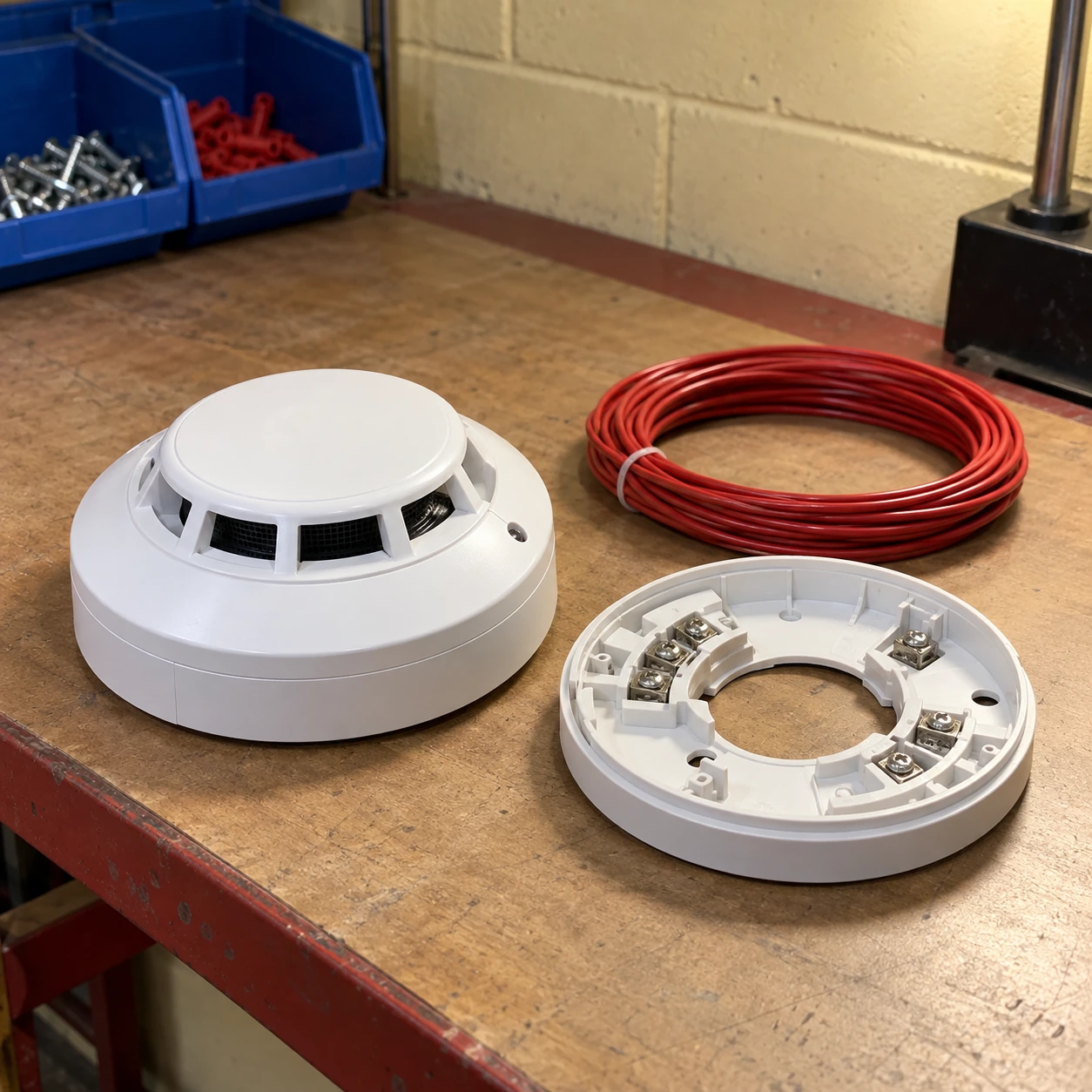
hardwired smoke detector
| Architecture | Conventional detector zone or compatible addressable loop |
|---|---|
| Sensing option | Photoelectric; supported multi-sensor configuration where specified |
| Housing / base sizes, diameter × height (mm) | 100 × 42 detector head; 100 × 50 standard base assembly |
| Conventional supply option | Nominal 24 V DC; documented 9–33 V DC range on selected families |
| Alternative addressable supply | Panel-specific operating range and signalling protocol |
| Connection accessories | Matching standard, isolating or sounder base as supported by the system |
| Cable / termination | Terminal type, conductor capacity and cable specification determined by the approved circuit design |
| Power resilience | Panel power supply and standby arrangement sized for the complete connected system |
These options concern low-voltage commercial systems. Do not connect a low-voltage detector to mains electricity. Mains-powered alarms belong to a different installation architecture.
Detector/base combinations and installation accessories can be customized for your approved wired fire alarm system.
For commercial and industrial premises, a hardwired smoke detector is selected as part of a supervised fire alarm system. The wiring carries a defined power and signalling arrangement; a round head that physically fits is not necessarily an electrical replacement.
Begin with the circuit, not the connector shape
Conventional and addressable systems report events in different ways. A conventional zone normally identifies an affected circuit or area; an addressable loop can identify individual devices through its supported protocol. The panel must recognize the selected detector and correctly supervise the connection.
Two-wire and four-wire descriptions are also architecture-specific. They cannot be interpreted as a universal wiring diagram. Installation and circuit alteration belong with the qualified fire alarm contractor using the exact panel and detector instructions.
The base is a functional part of the order
A base can provide a simple connection, short-circuit isolation, a sounder or other supported function. Changing it can therefore change more than the mounting height. Specify the approved head-and-base pairing, including any junction box and cable-entry requirements.
On a replacement job, identify whether the existing base may remain. Saving a small amount on a head-only order is unhelpful if the delivery cannot be commissioned on the installed base.
Adding devices changes the circuit load
The designer must account for standby and alarm current, cable characteristics, sounder loads and the panel's supported device limits. A spare physical position on the ceiling does not mean spare electrical capacity is available.
Keep the intended operation documented: which device reports which location, which outputs operate, and how power or connection faults are indicated. A successful local LED test is not a complete system acceptance test.
Plan the replacement around continued protection
Identify
Record the panel, detector, base and location. Include the known fault or reason for replacement instead of ordering solely from the front cover.
Coordinate
Arrange the service window and any necessary impairment measures through the responsible site personnel. Avoid unplanned disconnection of an occupied area.
Restore
Commission the supported assembly, verify the intended alarm and fault reporting, and update the device schedule before closing the work.
For individual device identification and maintenance reporting, the smart smoke detector page discusses compatible addressable and supervised wireless options. “Smart” features are useful only when the rest of the system supports them.
Detector/base combinations and installation accessories can be customized for your approved wired fire alarm system.