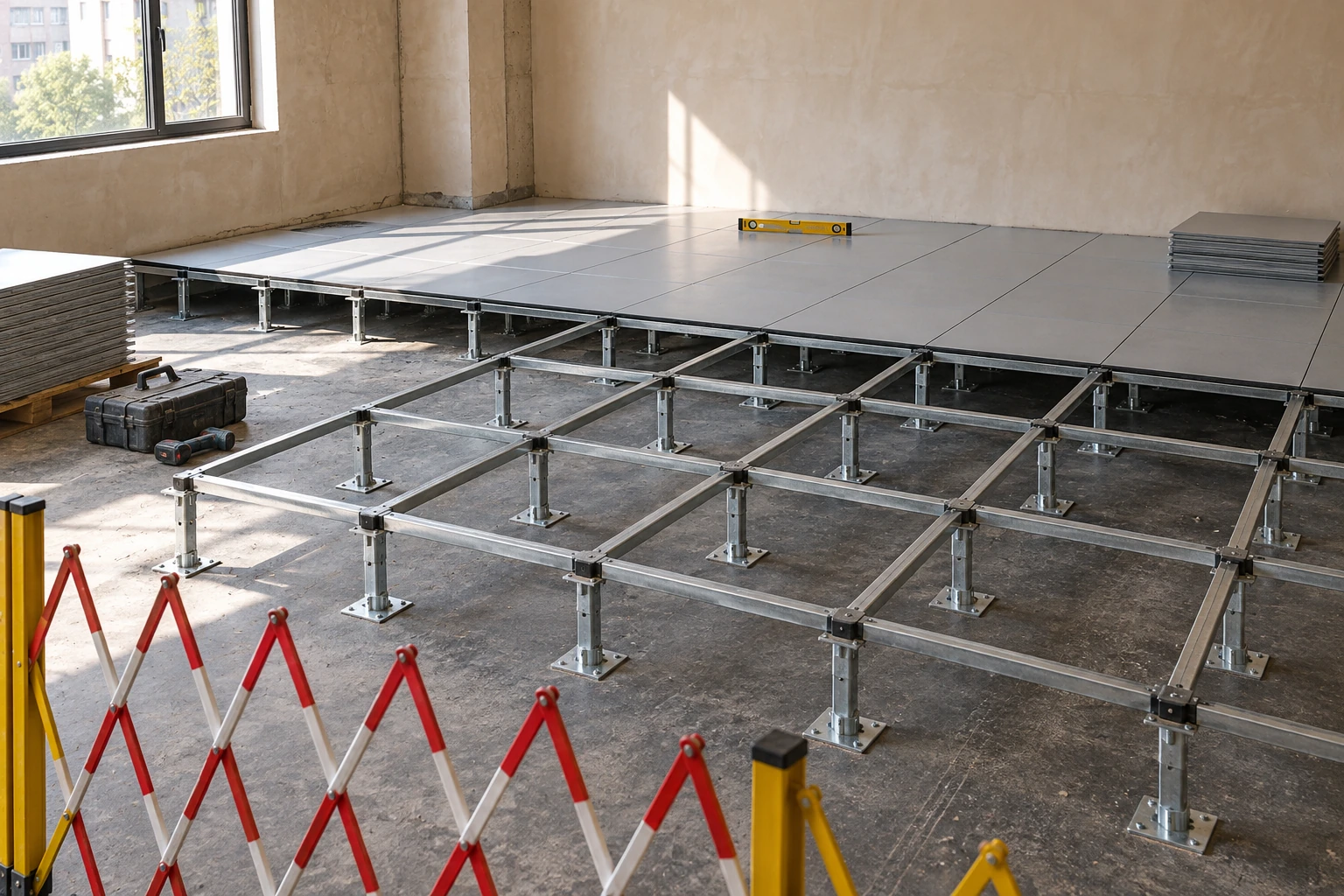
Raised Access Flooring
raised access flooring contractors
| Grid options | 600 × 600 mm metric; separate 609.6 × 609.6 mm / 24 × 24 in system |
|---|---|
| Metric panel constructions | 31 mm encapsulated or 40 mm faced wood-core assemblies |
| Floor height option | 40 mm faced assembly: 70–1320 mm finished floor height across support families |
| Understructure | Matched adjustable pedestals and specified stringer or restraint arrangement |
| Site interfaces | Perimeters, thresholds, partitions, service boxes and supported penetrations |
| Installation documents | Set-out drawing, component schedule and selected system instructions |
| Handover information | As-installed layout, component identification and access procedure |
The material package and site installation scope must be agreed separately. Fixing design, substrate acceptance and special supports depend on the selected assembly and project conditions.
The floor package and interface schedule can be configured for the project layout, installation sequence and operating requirements.
Raised access flooring contractors coordinate the material system with the real building. The essential work is to establish a sound substrate, maintain one level datum and resolve the interfaces that cannot be solved by laying standard panels alone.
Release the area for flooring at the right time
Before setting out, establish whether the slab and surface treatment are ready for the chosen fixing method. Wet trades, dust-generating work and uncontrolled moisture can interfere with installation. Store components in the conditions specified for the selected construction and keep damaged materials out of the assembly.
Agree who accepts the substrate and who remedies defects. Otherwise the flooring package can arrive while the room remains unsuitable, creating repeated handling and pressure to proceed with incomplete preparation.
Coordinate the work in a useful order
- Survey and establish the datum. Check slab levels and fixed thresholds against the required walking surface. Identify high points before support families are finalized.
- Set out the grid. Balance perimeter cuts and coordinate columns, partition lines and service openings. Keep special support locations visible on the drawing.
- Install the matched understructure. Follow the system's fixing, adjustment, restraint and curing requirements. Protect completed supports from damage by other trades.
- Close and check the floor. Confirm panel seating, surface levels, transitions and the condition of prepared openings before opening the area to normal traffic.
Keep delivery loads in the installation plan
Heavy cabinets and machinery may cross the floor only once, but that movement can govern the loading requirement. Wheel size, contact area, route and turning points matter. Plan protection and any temporary measures from the project's load assessment rather than assuming a general room rating covers delivery.
Stage completed zones so materials can reach the work without repeatedly crossing unfinished openings. Maintain barriers and safe alternative routes while panels are removed.
Agree the boundary with other trades
Electrical and mechanical contractors need access to the void, but they should not remove supports or enlarge openings without a coordinated detail. Partitions and equipment bases may require independent support. Floor installation drawings and service drawings should describe the same interfaces.
Changes after setting out should update the record so a maintenance team does not discover an undocumented opening or displaced pedestal later.
Handover should explain how to keep the floor working
Provide the as-installed component schedule, special support locations, lifting method and limits on opening panels during maintenance. Identify spare panels and access tools. Record any remaining restrictions before the room is released for equipment installation.
A contractor comparison should state responsibility for substrate preparation, special framing, transitions and protection of completed work. Review the project scope comparison when supply, installation and service coordination are divided between different companies.
The floor package and interface schedule can be configured for the project layout, installation sequence and operating requirements.