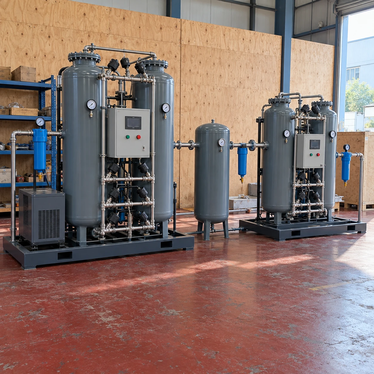
Nitrogen Generators
nitrogen generator systems
| System arrangements | Central supply, dedicated point-of-use units or expandable parallel modules |
|---|---|
| PSA module W × D × H (mm) | 775 × 840 × 2015; 1400 × 840 × 2015; 1421 × 970 × 2015 |
| Membrane module W × D × H (mm) | 820 × 772 × 2090; 820 × 1470 × 2090 |
| Duty allocation | Common-quality distribution or separate supplies for different gas specifications |
| Control strategy | Lead/lag operation, demand-based sequencing and maintenance isolation options |
| Storage and backup | Shared or dedicated receivers with an independently specified backup interface |
| Utility integration | Compressed-air capacity, air treatment, electrical supply and heat rejection |
| Expansion provisions | Space, pipe capacity, connection points and control allowance for additional modules |
Module dimensions are external W × D × H and do not represent a complete multi-unit installation. Shared utilities, access aisles and gas storage require separate layout planning.
Nitrogen generator systems can be customized around separate process duties, continuity requirements and planned expansion.
Nitrogen generator systems can be arranged around one central supply or several separate consumers. The right architecture depends on how much gas is used, where it is needed, whether quality requirements differ and what must keep running during maintenance. Adding another generator only helps if the supporting utilities and distribution can use it effectively.
Choose an architecture that fits the consumers
Central generation
A central plant can serve several consumers through one distribution network. It can simplify routine attention, but long pipe runs, pressure losses and a common outage affect more than one operation. Size the main for coincident demand and keep critical branches identifiable.
Dedicated supply
Separate units can keep an analytical instrument or a distinct gas-quality duty independent of the main plant. This reduces some shared dependencies, while adding local maintenance, heat and potentially several air or power connections.
Parallel modules
Several modules can match a changing load or support staged expansion. Their controls need to coordinate production and prevent unsuitable gas from entering a common header. Reserve capacity depends on what remains available when a module is isolated.
Two generators do not automatically provide two independent supplies
Both may depend on the same compressor, dryer, power circuit, quality analyser or distribution header. A fault in a shared item can stop the entire arrangement. Review the path from air intake to the critical consumer to identify what a standby unit actually protects.
For a duty that cannot tolerate interruption, define the required duration of backup and the acceptable changeover behaviour. A receiver covers a finite interruption; a separate gas source needs suitable regulation, isolation and an agreed connection arrangement. Test the changeover against the process requirements during commissioning.
Reserve more than a space for the next module
Expansion may require additional compressed air, treatment capacity, electrical capacity and cooling. It may also change the pressure loss through a common filter or main. An empty floor position is useful only when these supporting items can accommodate the added load.
Plan isolation points and a maintenance route so that a module can be serviced without dismantling neighbouring equipment. Decide which quality and pressure measurements are shared and which belong to individual branches. Clear ownership of these interfaces helps avoid gaps between equipment suppliers.
shengtongJH can coordinate a comparison using the consumer list, quality requirements, operating overlap and acceptable interruption time. For the component interfaces within one complete supply package, see nitrogen generator system.
Nitrogen generator systems can be customized around separate process duties, continuity requirements and planned expansion.