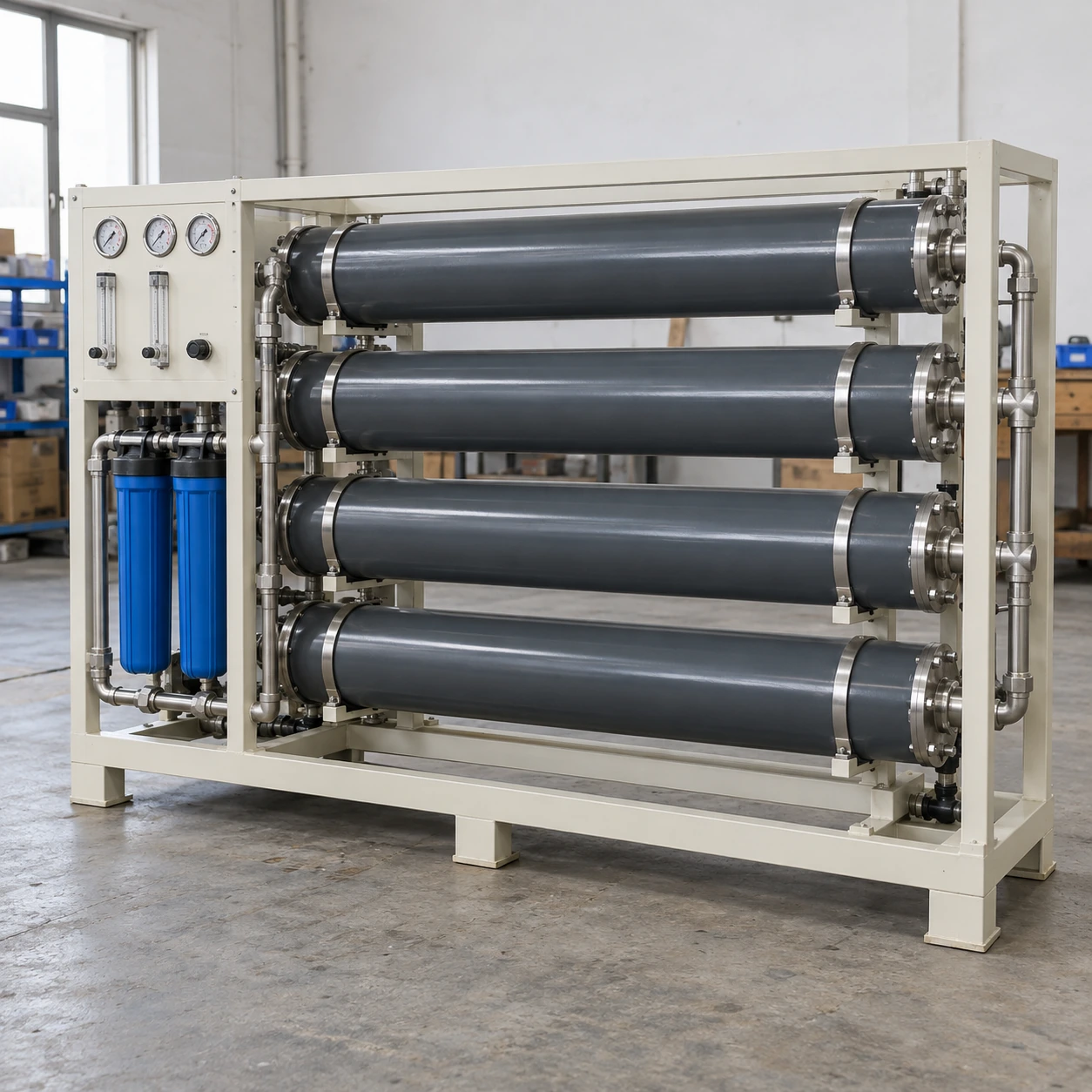
Nitrogen Generators
membrane nitrogen generator
| Separation technology | Enclosed hollow-fibre membrane modules |
|---|---|
| Nitrogen quality selections | 95%, 97%, 99% or 99.5%, subject to module and operating conditions |
| Assembly formats | Compact enclosed unit or modular rack |
| Compact external W × D × H (mm) | 560 × 285 × 1150 |
| Larger external W × D × H (mm) | 820 × 772 × 2090; 820 × 1470 × 2090 |
| Feed air | Dry, filtered compressed air with oil and particle control to the module specification |
| Flow and pressure | Selected together with purity and inlet temperature; regulated outlet arrangement |
| Instruments and connections | Pressure gauges, flow indication, oxygen analysis and suitable permeate discharge routing |
Listed dimensions exclude the air compressor, external receiver and maintenance access. Increasing the purity setting can reduce the product flow available from the same membrane assembly.
Membrane area, enclosure format and gas interfaces can be customized for the required nitrogen quality and consumption profile.
A membrane nitrogen generator passes conditioned compressed air through hollow-fibre modules. Oxygen and other faster-permeating gases leave through the membrane, while a nitrogen-rich stream continues to the product outlet. The result is a compact gas source whose flow must be matched to the required residual oxygen level.
The separation happens across the fibres
The membrane provides a large separation surface inside a small housing. Gas components move through that surface at different rates; the unit is not simply a particle filter with a nitrogen label. The product outlet and the permeate outlet have different functions and both belong in the installation layout.
A membrane package can provide a relatively simple continuous gas path. It still depends on suitable inlet treatment, sound connections and monitoring of the condition that matters to the application.
Purity and useful flow move together
Reducing the residual oxygen in the product stream generally means accepting less product flow from the same membrane area or supplying a larger assembly. Compare offers at the required quality and the same feed-air conditions. A high flow quoted at a lower purity should not be treated as available at the strictest setting.
Inlet pressure and temperature also influence performance. Use conditions representative of the installation, including the seasonal environment, rather than selecting solely from an attractive maximum figure.
Protect the modules with suitable air treatment
Liquid carryover, particles and unsuitable oil contamination can interfere with a membrane package. Identify the required filtration and drying arrangement before connecting to a plant air header. Existing compressed air should be assessed at the intended connection under demand.
Provide drains and access to replacement filter elements. A pressure drop that develops across neglected treatment equipment can reduce the conditions available at the membrane even if the compressor pressure display appears satisfactory. Maintenance should follow the selected module and treatment equipment instructions.
Fit the exhaust and service route into the cabinet choice
The separated stream can be oxygen enriched. The discharge location and the nitrogen outlet both need a suitable assessment; neither should simply be directed into a poorly ventilated enclosure. The equipment arrangement must also allow replacement of a complete module without dismantling unrelated plant pipework.
Where the process requires substantially lower residual oxygen, compare an appropriately specified PSA nitrogen generator. Where compactness and the membrane purity range fit the duty, provide the demand, inlet-air condition and available installation space so shengtongJH can coordinate a suitable package.
Membrane area, enclosure format and gas interfaces can be customized for the required nitrogen quality and consumption profile.