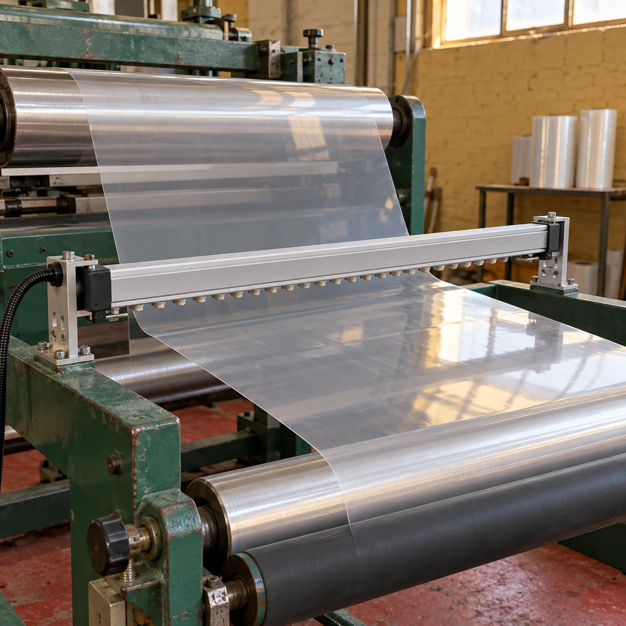
Ionizing Bars
ionizing bar static eliminator
| Process duties | Film unwinding, converting, sheet feeding and packaging-material handling |
|---|---|
| External L × W × H (mm) | 500 × 22 × 41.5; 1000 × 22 × 41.5; 1500 × 22 × 41.5 |
| Distance configurations | Close-range 25–100 mm or longer-range 100–500 mm designs, selected for the process |
| Power arrangement | 24 V DC input with integrated high-voltage generation in compatible bar configurations |
| Emitter pitch options (mm) | 25 or 50, according to the selected short- or longer-range design |
| Machine connection | Matched power cable, remote enable and operating/fault indication options |
| Mechanical mounting | Adjustable rail or T-slot fixings with appropriate support along the bar |
| Acceptance basis | Residual charge at the material, checked across the width and at the intended production speed |
The compact profile and distance ranges describe different available configurations, not a universal operating envelope. Mountings, cable exits and maintenance access are additional to the bar dimensions.
The static-elimination arrangement can be customized for the material path, production speed, available clearance and machine integration.
An ionizing bar static eliminator helps reduce problems caused by charged film, sheets and plastic components. Sticking at a roller, poor feeding or dust attraction can have a static contribution, but the useful installation depends on finding where charge is generated and where it interferes with production.
Locate the charge source before choosing a position
Contact and separation during unwinding, roller passage or peeling can leave an insulating material charged. Treating one position does not prevent a later contact from generating charge again. Follow the material through the machine and compare measurements before and after the suspected source.
Place the treatment where it can influence the next troublesome operation. A bar near the delivery end may help stacking but do little for a feeding problem much earlier in the line. If several problems occur at different stages, assess them separately.
Give the bar a useful treatment zone
- Expose the material: keep the ion path clear of guards, brackets and other obstructions while maintaining machine guarding.
- Review the surroundings: nearby grounded metal can collect ions that should reach the material. A supported web against a metal roller can behave differently from a free span.
- Allow for movement: film flutter and changing roll geometry can alter the gap. Choose a mounting position and bar type that accommodate the real movement.
- Check the full width: a satisfactory centre reading does not demonstrate that both edges receive enough treatment.
Verify at the production condition that causes the problem
A slow trial gives the material more exposure time than a fast production run. Test the intended line speed, representative materials and realistic environmental conditions. Use a consistent measurement arrangement so that changes in distance or instrument position do not hide the result.
If performance drops as speed rises, investigate treatment time, bar location and output configuration together. A larger voltage number on a datasheet does not by itself establish better neutralization in the machine.
Distinguish charge control from particle removal
Neutralizing charge can reduce electrostatic attraction, but it does not collect dust or remove all particles already attached to a surface. A cleaning duty may need a coordinated air-delivery and extraction arrangement. Avoid simply blowing contamination into the next process.
For solvent vapours or combustible dust, the installation requires equipment appropriate to the actual hazardous-area assessment. Ordinary industrial bar configurations are not a claim of explosion protection.
Send shengtongJH the material width, travel path, speed and the location of the observed problem for a focused equipment scope. For stationary ESD-sensitive work, see static ionizing bar.
The static-elimination arrangement can be customized for the material path, production speed, available clearance and machine integration.