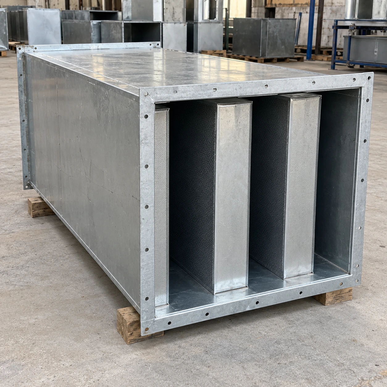
Duct Silencers
hvac duct silencer
| Brand | shengtongJH |
|---|---|
| Arrangement | Rectangular splitter attenuator for supply or return duct |
| Connection W × H | 500 × 400 / 600 × 600 / 800 × 600 mm |
| Length along airflow | 750 / 1000 / 1500 mm |
| Casing options | Galvanized steel or stainless steel |
| Splitter construction | Protected absorptive baffles; thickness and spacing selected together |
| Air volume | Matched to AHU operating duty and part-load conditions |
| Acoustic selection | Frequency-band insertion loss and regenerated sound |
| Pressure selection | Silencer and transition losses included in fan calculation |
| Connection style | Matching flanged duct joints |
| Thermal provisions | External insulation and vapour control where required by the air conditions |
Acoustic and pressure performance must refer to the same selected geometry and airflow. No general dB or Pa figure applies to every listed size.
Connection dimensions, acoustic length, baffle arrangement and thermal provisions can be customized to the HVAC system.
An HVAC duct silencer belongs in the air-handling system selection, alongside the fan, filters, coils and terminals. Planning it early avoids a late noise correction that consumes the pressure or space needed by the rest of the system.
Start with the fan and the receiving space
A fan sound-power schedule gives a more useful starting point than a single overall noise figure. The duct route, branches, terminal locations and receiving-space requirement then determine where attenuation is needed. Low-frequency fan sound and high-frequency airflow noise may call for different treatment.
Keep supply and return paths separate in the assessment. A quiet supply route does not compensate for an untreated return opening facing a noisy plant area. Sound can also escape through casing and penetrations, so the duct silencer should form part of a coordinated solution.
Reserve pressure for acoustic treatment
Every component adds resistance. If the fan is selected before the silencer and transitions are included, the final system may deliver less air than intended. Raising fan speed later can increase power and noise, undermining the reason for adding attenuation.
Compare candidate constructions at the same airflow and account for inlet conditions. A low catalogue pressure drop under uniform flow does not guarantee the same installation result after a sharp elbow.
Coordinate the installation envelope
The body needs room for flanges, transitions, insulation and independent supports. Keep coil withdrawal, filter replacement and access-door movement clear. A dimension that fits on a plan may still obstruct the maintenance route beside an air-handling unit.
Make commissioning criteria useful
Record the selected duty, expected pressure loss and relevant acoustic data with the equipment schedule. During commissioning, establish that the system is delivering its intended airflow before judging noise performance. An unusually quiet system operating well below design flow is not a successful result.
shengtongJH supplies through a sourcing process: the purchase should identify the construction and supporting data required. For site coordination, the installation page explains support, joint and access decisions that need to be settled before delivery.
Connection dimensions, acoustic length, baffle arrangement and thermal provisions can be customized to the HVAC system.