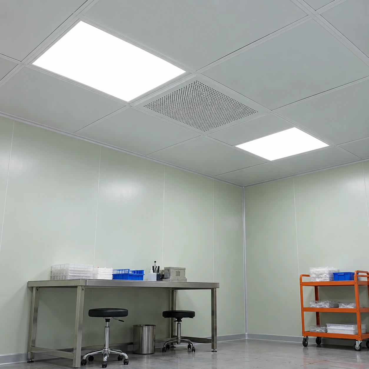
Cleanroom Lighting
cleanroom lighting systems
| Ceiling module choices | 600 × 600; 300 × 1200; 600 × 1200 mm (nominal W × L) |
|---|---|
| Luminaire arrangement | Square or linear fixtures placed around workstations, equipment and air terminals |
| Electrical grouping | Circuits and switching zones defined by work area and operating needs |
| Control architecture | Switched lighting or compatible addressable drivers, controller, input devices and bus supply |
| Emergency interface | Dedicated emergency arrangement and testing access selected for the project |
| Design information | Ceiling plan, luminaire schedule, photometric layout, circuit/control references and service access |
These are system configuration choices, not a fixed room-size package. Fixture count, output, circuit loading and controls depend on the selected equipment and project design.
Lighting layouts, fixture combinations, control zones and service arrangements can be customized for the room and production workflow.
A cleanroom lighting system brings together luminaires, power distribution, controls and the physical ceiling layout. The useful result is a coordinated installation that supports the work and remains understandable to operators and maintenance staff.
Use one coordinated ceiling plan
The ceiling drawing should show lights alongside filtration, air terminals, access panels and structural supports. A lighting arrangement developed without these services can be difficult to install and can force last-minute changes that alter the light at the work surface.
Keep access routes visible in the plan. A driver cover that can open on an empty ceiling may become inaccessible after a duct or cable tray is installed. Coordinate the selected air terminals and fan filter units with the lighting positions, while preserving the airflow and service requirements of each system.
Give each control zone a clear purpose
Zones can follow workstations, circulation routes or operational states. A cleaning setting may need a different light level from normal production, while an unoccupied area may permit reduced output. Define those behaviours with the process team instead of leaving the installer to infer them from the fixture locations.
An addressable driver provides one part of a control system. A functioning arrangement also needs the appropriate controller, user inputs or sensors, communication power and commissioning. Buying compatible drivers alone does not create the intended switching groups or scenes.
Supply and control are separate decisions
The supply circuit powers the luminaires; the control arrangement determines how they respond. Confirm the selected drivers, circuit loading and behaviour after power is restored. Critical tasks should not depend on an undocumented default setting or an occupancy sensor that does not detect the actual work pattern.
Emergency operation needs its own design
Normal lighting controls do not define emergency coverage, duration or testing. Coordinate the emergency strategy with the responsible project designer and retain access to its components. A normal dimming scene should not be used as evidence of compliant emergency operation.
Commission against the intended use
- Confirm the installed schedule: fixture, optic, driver and mounting arrangement should match the approved selections.
- Check the light where work happens: use the specified task planes and project criteria, with relevant equipment in position.
- Exercise the controls: verify groups, scenes, overrides and restoration behaviour without leaving unexplained settings.
- Hand over usable records: retain the final layout, addresses where applicable, component details and maintenance instructions.
Lighting checks and room cleanliness qualification answer different questions. Keep both in the project plan, but do not treat completion of one as proof of the other.
Lighting layouts, fixture combinations, control zones and service arrangements can be customized for the room and production workflow.