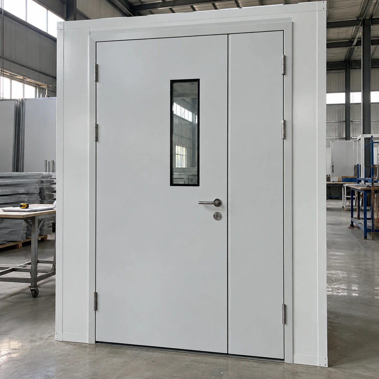
Cleanroom Doors / Windows
custom cleanroom doors
| Door format | Single leaf; equal or unequal double leaf |
|---|---|
| Nominal door sizes, W × H × T (mm) | 900 × 2100 × 42; 1828 × 2100 × 42 |
| Leaf finish | Powder-coated steel, stainless steel or aluminium skin |
| Frame | Aluminium profile or formed steel; matched to the wall system |
| Sealing | Perimeter gasket; bottom drop seal option |
| Glazing and hardware | Flush vision panel; lever or push plate; closer and access-control options |
Nominal door sizes are not clear-passage or wall-opening dimensions. Frame envelope, handing and usable opening are defined by the selected doorset drawing.
The doorset can be customised for the measured opening, room interface and actual use.
Custom cleanroom doors resolve a specific mismatch between the opening, the traffic route and a standard assembly. Useful customisation starts with that mismatch, then carries it through the frame, leaf and hardware details.
Customise the interface that causes the problem
A thicker existing wall may need a different frame throat, not a wider leaf. An equipment route may need a removable secondary leaf, not a permanently oversized personnel entrance. A room with limited swing space may need a sliding arrangement, which changes the wall support and service zone as well as the door itself.
Identifying the cause prevents a special size from being ordered without solving the real constraint. The best arrangement is often a standard hardware family fitted to a carefully adapted interface, keeping later servicing straightforward.
Turn site measurements into an agreed drawing
- Establish the finished opening. Record width and height at more than one position, wall thickness, floor level and any out-of-square condition. The bare construction opening may change after linings or floor finishes are installed.
- Define the useful passage. Show the leaf at its actual operating angle or parked position, including handles, closers and the route of the largest load.
- Resolve the connection. Identify the supporting structure, frame fixing, perimeter closure and access for installation tools.
- Freeze the hardware arrangement. Door handing, vision-panel position, lock function and any control cable routes belong on the same approved schedule.
Changes have consequences
Making a leaf taller or adding a large vision pane changes its stiffness, weight distribution and hinge loading. Increasing a sliding opening changes the rail and parking requirements. These are reasons to review the assembly, rather than simply scaling every dimension in a drawing.
For fire-resisting or containment duties, the permitted construction may place tighter limits on customisation. A special dimension or hardware substitution must remain inside the relevant evidence or be assessed through an appropriate route.
Keep installation tolerances visible
The frame outside dimension, structural opening and clear passage are different. A drawing that shows only one of them leaves the installer to invent the others. The location of the finished floor is especially important for drop seals and low-clearance leaves.
A representative corner or trial assembly can be useful where the existing wall is unusual. It allows the fixing, trim and cleaning access to be resolved before all openings are produced.
Custom does not have to mean difficult to maintain
Use accessible seal channels and identifiable fittings wherever the duty permits. Keep a record of what is standard and what is specific to the opening. A later gasket replacement should not require reverse-engineering the entire door.
For quotation, an opening schedule and marked-up plan are more informative than a photograph alone. The enquiry form can be used to describe the unusual interface, equipment route and operating requirement so the supply scope addresses the actual problem.
The doorset can be customised for the measured opening, room interface and actual use.